Endoprosthesis and delivery system for its placement within a patients vessel and uses for this endoprosthesis and delivery system

a technology of endoprosthesis and patient vessel, which is applied in the field of endoprosthesis and delivery system, can solve the problems of mass hemorrhage, rupture of aneurysm, loss of blood,

Inactive Publication Date: 2009-06-04
NETO MELCHIADES CUNHA +1
View PDF23 Cites 6 Cited by
  • Summary
  • Abstract
  • Description
  • Claims
  • Application Information

AI Technical Summary

Benefits of technology

[0023]A third embodiment of the invention relates to the use of the delivery system for implanting an endoprosthesis in a patient needing such treatment wherein the system comprises (a) loading and fixing the invention endoprosthesis inside the delivery system by means of the proximal and distal cones; (b) positioning of the delivery system bearing the the invention endoprosthesis at the intended position within the vessel; (c) releasing the endoprosthesis from the external sheath by uncoupling the proximal support while maintaining the distal support unaltered; (d) correcting inadequa

Problems solved by technology

Failure to treat this condition may eventually result in the rupture of the dilatation (aneurysm) causing a massive haemorrhage in a very short period of time with fatal consequences.
The disruptions caused by of the abdominal aortic aneurysms are very serious and may lead to death.
Such a procedure requires a surgical incision to allow access to the vessel, which may result in rupture of the aneurysm due to the sudden reduction in the external pressure exerted by the neighboring organs and tissues which are displaced during acess procedure.
Quite apart from this serious issue, other risk factors include loss of blood and consequent weakness, anuria and low blood pressure associated to the abdominal aortic aneurysm.
However, despite the advances represented by the use of stent and stent-graft devices, they have revealed failings both with regard their implanting processes and performance.
Type I failings are related to the occurrence of leakage between the vascular endoprosthesis and the vessel walls in the area of the proximal aorta immediately above the aneurysm and, therefore, results in continued blood flow to the aneurysmal sac, which thus maintains the pressure at this point and favours continued expansion and consequent rupture of the aneurysm.
Type I failings may also be caused by the irregular shape of the vessel and/or calcified topography of the aorta lumen which results in poorly inserted circular prostheses in non-circular lumens of the aorta.
Type III failings are of mechanical origin and result from excessive wear of the metal/non-metal interface or the poor integrity of a connection or connections between the modular components of a prosthesis.
Lastly, the type IV failings are related to excessive porosity of the prosthesis walls which allows the blood to migrate through the walls despite the soundness of all mechanical seals and connections.
Although such a device does represent an advance compared to former techniques involving surgical procedures, it still presents failings related to its unfavourable displacement along the blood flow and the precision required when correctly positioning the device at the time of implant.
Despite this device being self-expanding and having appropriate flexibility at the region of bifurcation, it remains difficult to implant at the i

Method used


Image

  • Endoprosthesis and delivery system for its placement within a patients vessel and uses for this endoprosthesis and delivery system
  • Endoprosthesis and delivery system for its placement within a patients vessel and uses for this endoprosthesis and delivery system
  • Endoprosthesis and delivery system for its placement within a patients vessel and uses for this endoprosthesis and delivery system

Examples


second embodiment

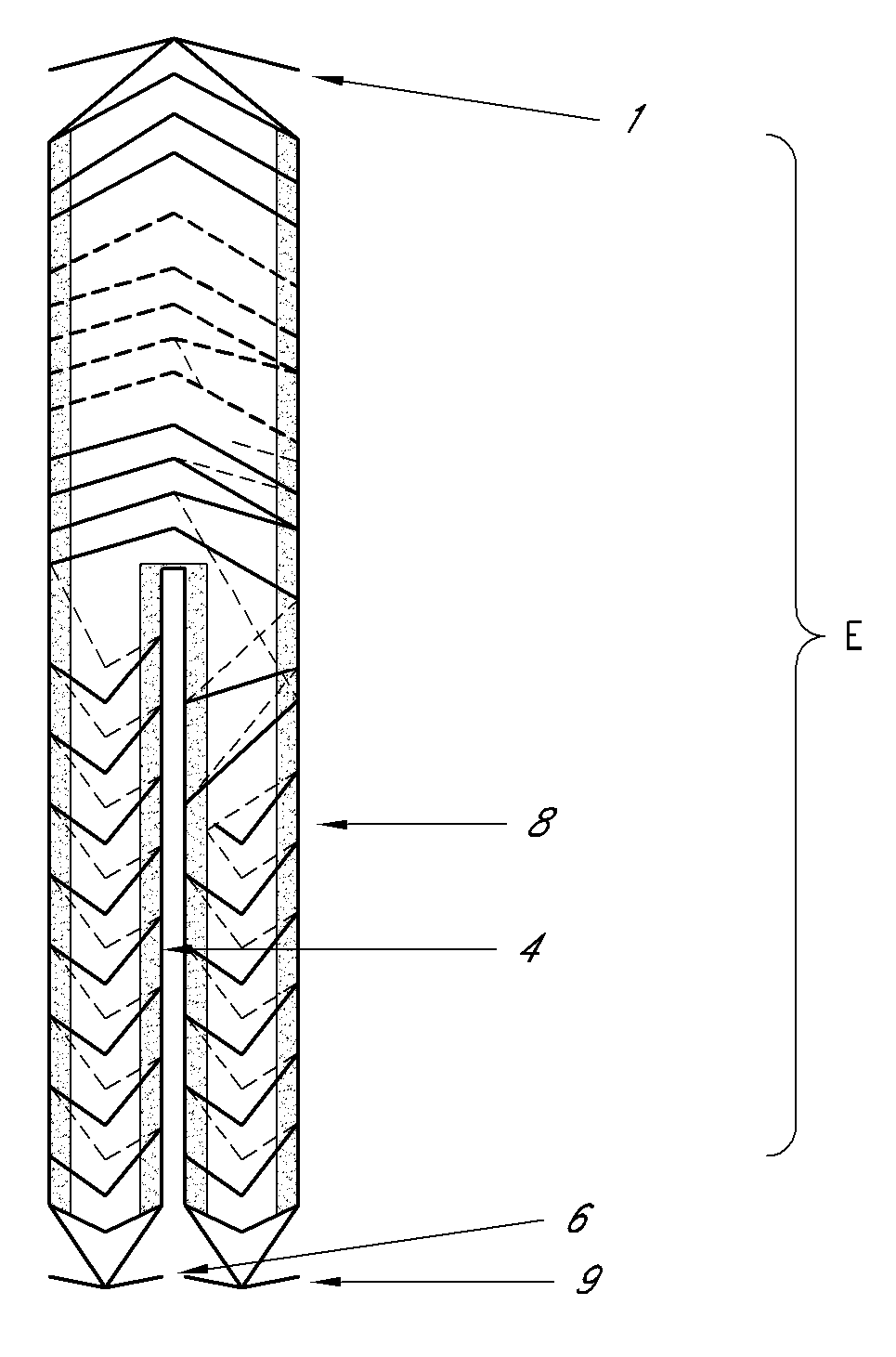
[0046]the present invention relates to a delivery system for delivering the endoprosthesis of the present invention to the intended place of implant within a vessel conveying biological fluids (e.g. blood) in a patient.

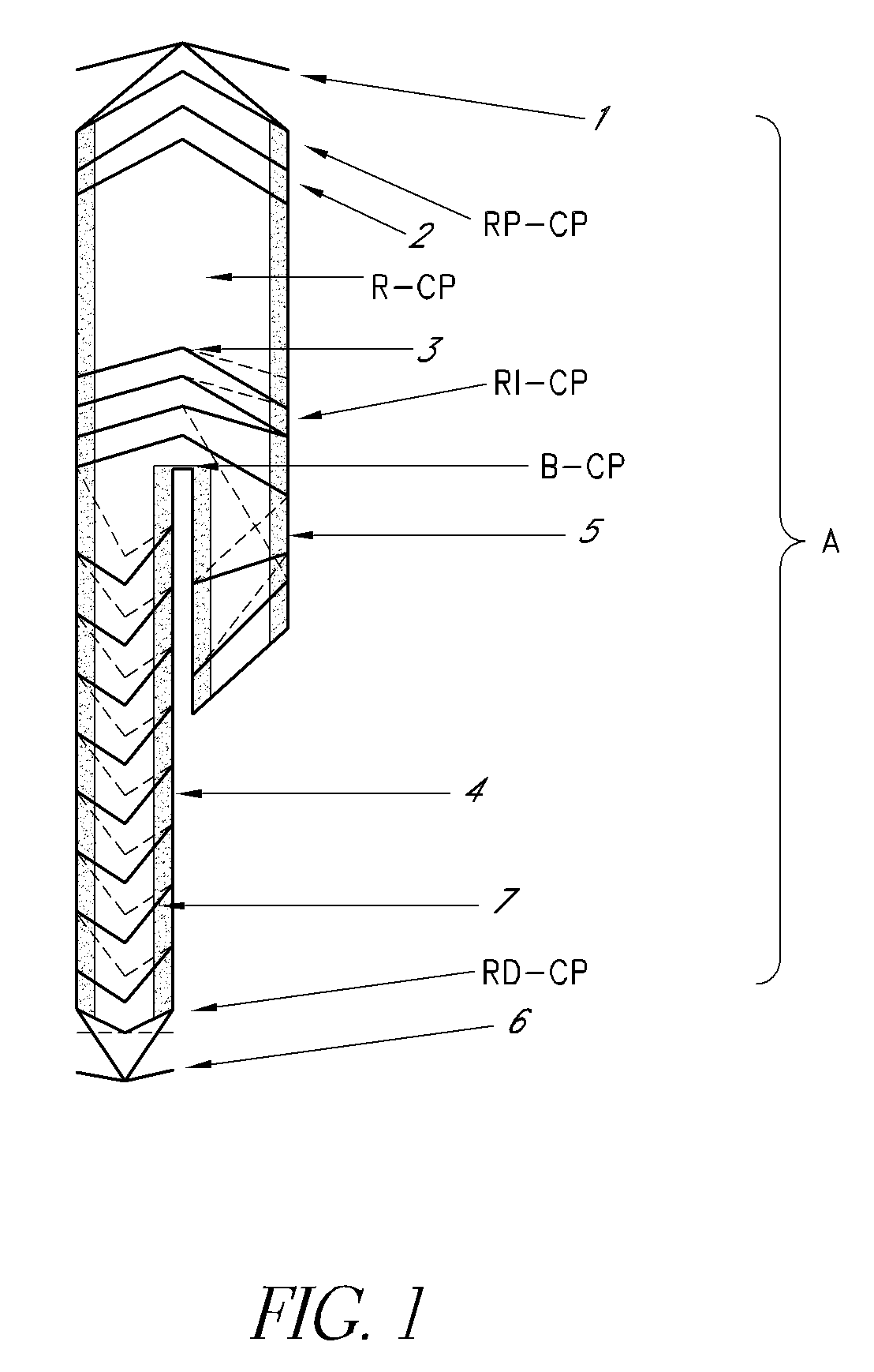
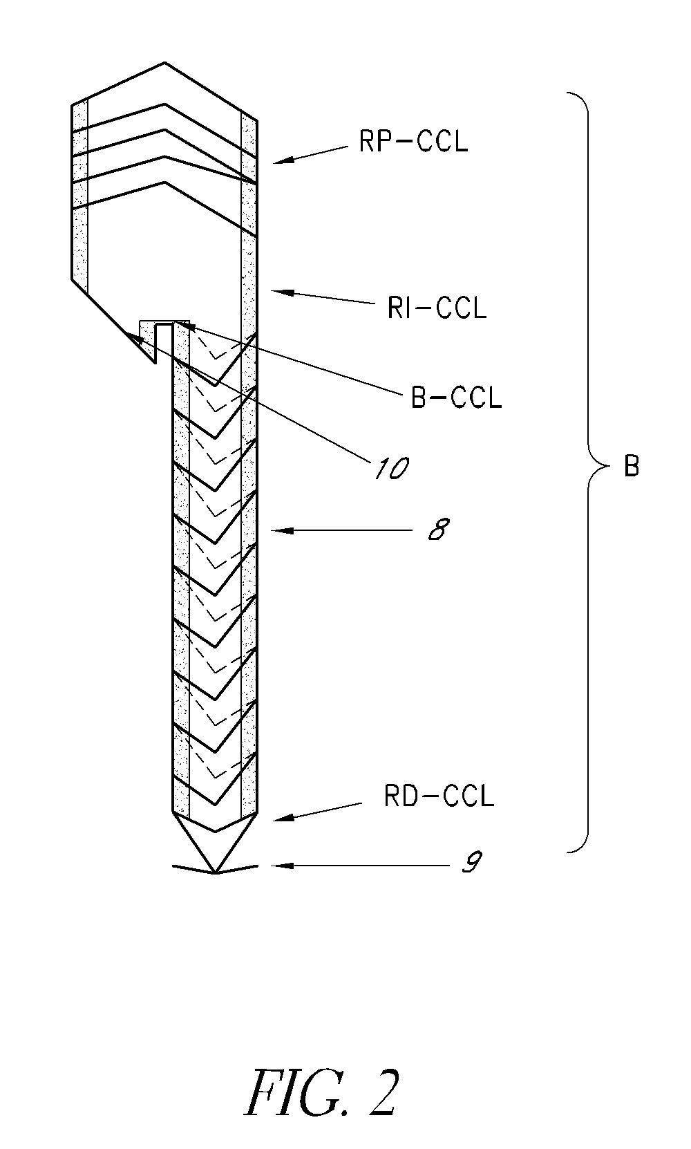
[0047]FIG. 4 shows the delivery system (S) for both bodies “A” and “B”, comprising a catheter with a distal and proximal endoprosthesis attachment device. This allows complete controle on the part of the surgeon when implanting the device. The delivery system (S) of the present invention comprises the following mechanisms for conveying, positioning, fine adjustment and attachment of the endoprosthesis (E) of the present invention: (a) proximal (S1) and distal supports (S2), (b) external sheath (S3), (c) proximal (S4) and distal cones (S5), (d) distal stent trigger (S6) and (e) proximal stent trigger (S7).

[0048]The proximal support (S1) is connected to the external sheath (S3) by the means of attachment of the latter, such as, for example, a flange. This configuration ...

third embodiment

[0051]The operation of the delivery system (S) of the present invention comprses the following consecutive steps: (i) loading and attaching the endoprosthesis (E) by means of the proximal (S4) and distal cones (S5), that are in turn connected to their respective proximal (S7) and distal (S6) free stent triggers. The endoprosthesis (E) is attached at both its proximal and distal extremities which allows any necessary correction in the case of innaccurate positioning during the release of the said endoprosthesis (E) or during the critical stages of the surgical procedures. the invention relates to the use of the delivery system for implanting an endoprosthesis (E) in a patient requiring such treatment. The procedure for use may be described in the following manner:[0052]the endoprosthesis (E) of the present invention is first loaded in the delivery system (S) of the present invention and connected to the proximal (S4) and distal cones (S5);[0053]once the delivery system loaded with th...


PUM


Abstract

The present invention relates to an endoprosthesis composed of (a) two complementary bodies, body “A” and (b) a body “B”, with the said bodies being formed by proximal, intermediate and distal regions and comprising a self-expanding structure of resistant and flexible material and a graft wherein the said bodies “A” and “B” have a bifurcation for use where a main vessel bifurcates into at least two secondary branches, such as in the case of the treatment of aneurysms in the abdominal aorta.
The invention further includes a delivery system for the endoprosthesis of the present invention, as well as its use in the treatment of aneurysms.

Description

CROSS-REFERENCES AND RELATED APPLICATIONS [0001]This application claims priority to Brazilian patent application No. PI 0704464-0 filed in Brazil on Nov. 30, 2007, the disclosure of which is expressly incorporated herein by reference in its entirety for any purpose.FIELD OF THE INVENTION [0002]The present invention relates overall to a device and a method for repairing the arterial system at the point where a principal artery bifurcates into at least two secondary arteries. More specifically, the invention is intended for the repair of an aneurysm in the vicinity of the aorta. One of the embodiments of the invention relates to a modular intravascular device termed a self-expanding percutaneous endoprosthesis used in the treatment of aneurysms, more specifically of the abdominal aorta. The said device is composed of two complementary bodies, namely, body “A” and body “B”, which both comprise self-expanding metal structures (a set of several stents) and a graft of appropriate tissue. ...

Claims


Application Information

Patent Timeline
IPC IPC(8): A61F2/06A61F2/84
CPCA61F2/07A61F2/954A61F2002/075A61F2/89A61F2002/067
Inventor SILVEIRA, PIERRE GALVAGNI
Owner NETO MELCHIADES CUNHA
Why Eureka
Try Eureka