Image-guided navigation employing navigated point computation method and system

a navigation point and computation method technology, applied in the field of image-guided navigation, can solve problems such as navigation errors and complicated image-guided navigation

Active Publication Date: 2009-06-04
STRYKER EURO OPERATIONS HLDG LLC
View PDF2 Cites 16 Cited by
  • Summary
  • Abstract
  • Description
  • Claims
  • Application Information

AI Technical Summary

Benefits of technology

[0006]A method of image-guided navigation, comprising: determining a final navigated point in a three-dimensional reconstructed coordinate system based at least partially on two or more navigated points in a coordinate system associated with a two-dimensional array of image pixels and without specifying a coordinate of each of the two or more navigated points in a direction orthogonal to the two-dimensional array of image pixels, wherein each of the two or more navigated points is for a different position of a C-arm gantry.
[0007]A method of image-guided navigation, comprising: manipulating a device inside a patient, wherein an electromagnetic sensor is fixed in relation to the device; transmitting a tracking signal; receiving the tracking signal; determining a position of the device in a three-dimensional reconstructed coordinate system associated with a reconstructed image using the tracking signal, wherein the position of the device is based at least partially on two or more navigated points in the three-dimensional reconstructed coordinate system, wherein each of the two or more navigated points was transformed from a coordinate system associated with a two-dimensional array of image pixels to the three-dimensional reconstructed coordinate system for a different position of a C-arm gantry, and wherein the position of the device is determined using only the X- and Z-coordinates of the two or more navigated points in the coordinate system associated with the two-dimensional array of image pixels; and projecting the position of the device onto the reconstructed image.

Problems solved by technology

As will be appreciated, image-guided navigation may be complicated by navigation error, which is perceived by the operator as the distance between the tip of the navigated device in the image and the true instrument position in the image.

Method used


Image

  • Image-guided navigation employing navigated point computation method and system
  • Image-guided navigation employing navigated point computation method and system
  • Image-guided navigation employing navigated point computation method and system

Examples


Embodiment Construction

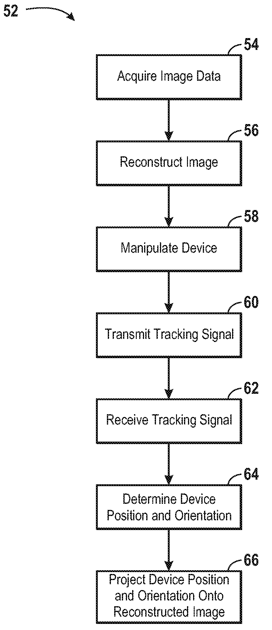
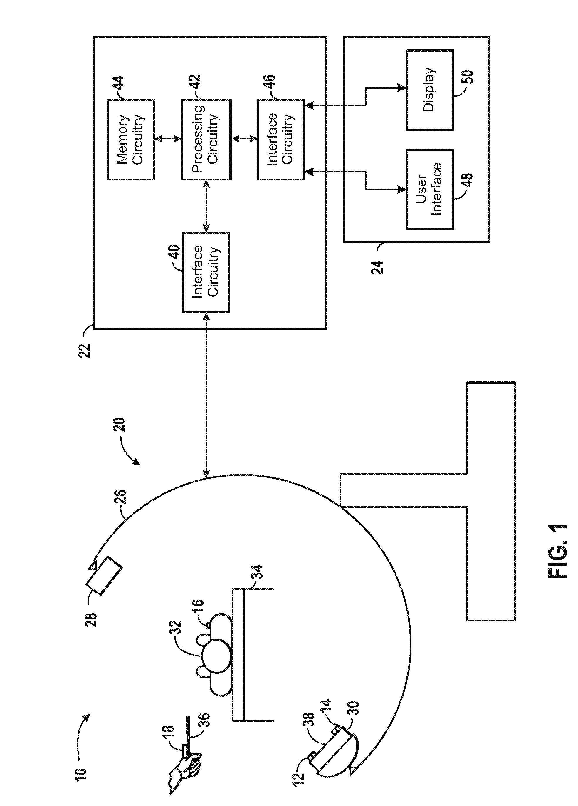
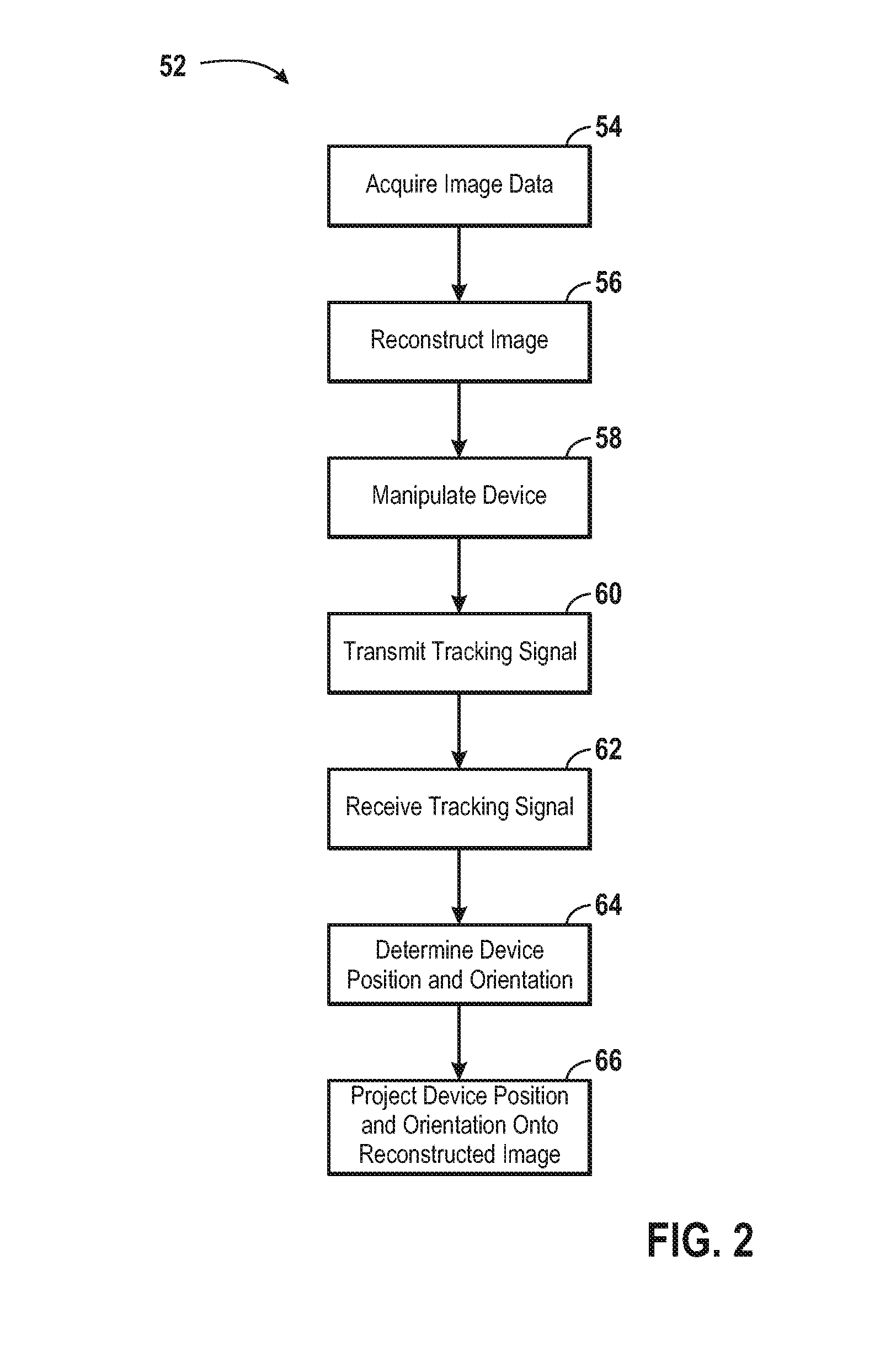
[0016]Referring now to FIG. 1, navigation system 10 is illustrated. In the illustrated embodiment, navigation system 10 comprises tracking components that include a plurality of electromagnetic (EM) sensors 12, 14, 16, and 18. Further, navigation system 10 includes an X-ray fluoroscopy system 20 for acquiring and processing image data. As illustrated, navigation system 10 further includes controller 22 and workstation 24.

[0017]X-ray fluoroscopy system 20 is illustrated as a C-arm system that includes a C-arm 26, an X-ray radiation source 28, and an X-ray detector 30. The X-ray radiation source 28 is mounted on the C-arm 26, and the X-ray detector 30 is mounted on the C-arm 26 in an opposing location from the X-ray radiation source 28. While in some systems the X-ray radiation source 28 and the X-ray detector 30 may be fixed, in a typical fluoroscopy system the C-arm 26 allows for movement of the X-ray radiation source 28 and the X-ray detector 30 about a patient 32. In operation, th...


PUM


Abstract

Provided is a method of image-guided navigation comprising determining a final navigated point in a three-dimensional reconstructed coordinate system based at least partially on two or more navigated points in a coordinate system associated with a two-dimensional array of image pixels and without specifying a coordinate of each of the two or more navigated points in a direction orthogonal to the two-dimensional array of image pixels, wherein each of the two or more navigated points is for a different position of a C-arm gantry. Also provided is an image-guided navigation system.

Description

BACKGROUND[0001]The present invention relates generally to image-guided navigation. More particularly, the present invention relates to methods and systems that employ a technique for determining a navigated point that uses an image-plane constraint to reduce navigation errors.[0002]Image-guided navigation systems typically include an imaging system and an electromagnetic tracker and have been used to provide an operator (e.g., a physician) with information to assist in the precise and rapid positioning of a medical (e.g., surgical) device in a patient's body. In general, an image may be displayed for the operator that includes a visualization of the patient's anatomy with an icon or image representing the device location projected thereon. As the device is positioned with respect to the patient's body, the displayed image may be updated to reflect the correct device location. The image of the patient's anatomy may be generated either prior to or during the medical or surgical proce...

Claims


Application Information

Patent Timeline
Patent Type & Authority Applications(United States)
IPC IPC(8): G06F17/11A61B5/00
CPCA61B6/4441A61B2019/5295A61B2019/5251A61B19/5244A61B2090/367A61B34/20A61B2034/2051
Inventor LITVIN, ANDREWHAMADEH, MOHAMED ALI
Owner STRYKER EURO OPERATIONS HLDG LLC
Why Eureka
Try Eureka