Vibration-Damping Control Apparatus and Vibration-Damping Control Method for Internal Combustion Engine

a control apparatus and internal combustion engine technology, applied in the direction of electric control, engine starters, machines/engines, etc., can solve the problems of insufficient reduction of intervals, and variation of torque, so as to reduce torque variation

Inactive Publication Date: 2009-06-11
HITACHI LTD
View PDF9 Cites 42 Cited by
  • Summary
  • Abstract
  • Description
  • Claims
  • Application Information

AI Technical Summary

Benefits of technology

[0008]The present invention has been accomplished in view of the above problems, and an object of the present invention is to reduce torque variation occurring when the combustion is temporarily stopped in some cylinders, using a rotating electric machine provided with at least one of functions of an electric motor and a generator.
[0011]controlling a variable valve mechanism which varies a valve lift amount of at least one of an intake valve and an exhaust valve of each cylinder in the Internal combustion engine, to thereby decrease the valve lift amount of at least one of the intake valve and the exhaust valve of each cylinder in which the combustion is temporarily stopped; and
[0012]controlling the rotating electric machine provided with at least one of functions of the electric motor and the generator, to thereby apply, to an output shaft, a torque for suppressing torque variation in the output shaft in the internal combustion engine at the time when the combustion is temporarily stopped in some cylinders.

Problems solved by technology

H7-189757, the torque variation due to the uneven explosion intervals cannot be reduced, and accordingly, the reduction in the vibration of the interval combustion engine might be insufficient.

Method used


Image

  • Vibration-Damping Control Apparatus and Vibration-Damping Control Method for Internal Combustion Engine
  • Vibration-Damping Control Apparatus and Vibration-Damping Control Method for Internal Combustion Engine
  • Vibration-Damping Control Apparatus and Vibration-Damping Control Method for Internal Combustion Engine

Examples


first embodiment

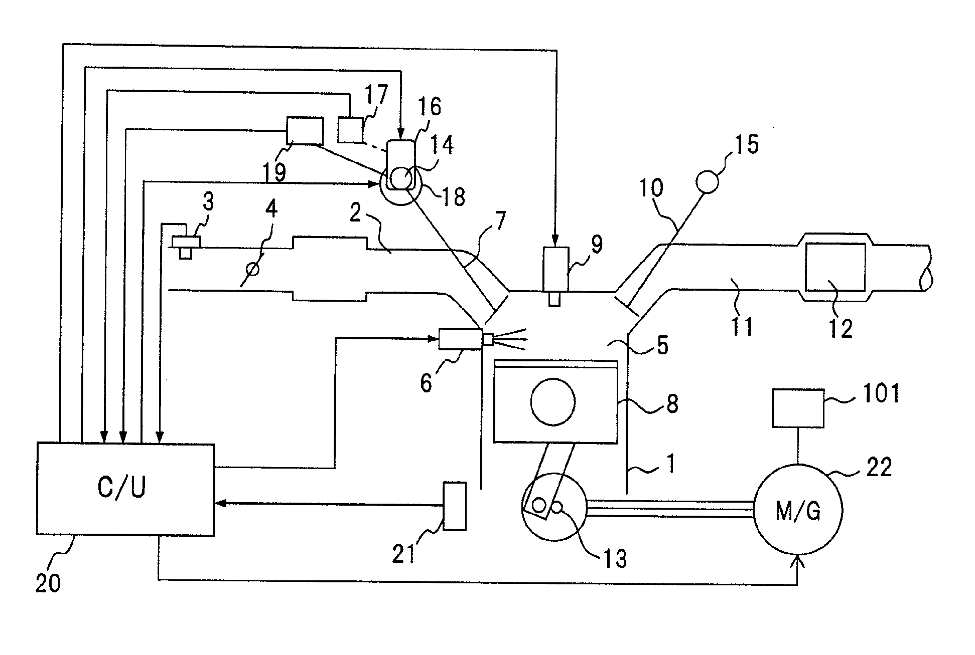
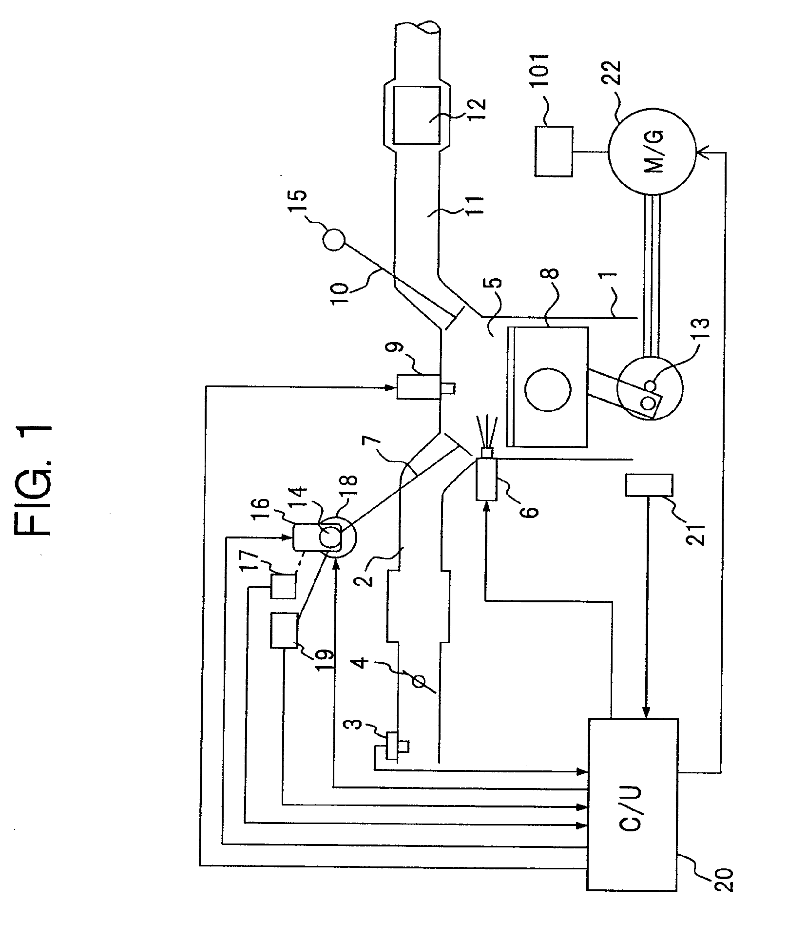
[0030]FIG. 1 is a diagram illustrating a system configuration of an internal combustion engine provided with a variable valve mechanism, according to the present invention.

[0031]In an intake passage 2 of an internal combustion engine 1, there is disposed an air flow meter 3 for detecting an intake air amount Q, and on the downstream side thereof, a throttle valve 4 which controls the intake air amount Q is disposed.

[0032]Further, there is disposed a fuel injection valve 6 which injects fuel into a combustion chamber 5 of each cylinder on the downstream of intake passage 2. The air-fuel mixture of the fuel injected from fuel injection valve 6 and the air sucked via throttle valve 4 and an intake valve 7 is compressed by a piston 8 in combustion chamber 5 to be spark ignited by an ignition plug 9 disposed in combustion chamber 5.

[0033]The combusted exhaust gas from internal combustion engine 1 is exhausted from combustion chamber 5 via an exhaust valve 10 to an exhaust passage 11, and...


PUM


Abstract

An apparatus and method of controlling vibration-damping for a vehicular internal combustion engine. The combustion is temporarily stopped in some cylinders among a plurality of cylinders, and the engine is operated by the remaining cylinders. Then, a variable valve mechanism which varies a valve lift amount of at least one of intake and exhaust valves of each cylinder is controlled, to decrease the valve lift amount of at least one of the intake and exhaust valves of each cylinder in which the combustion is temporarily stopped. Further, a rotating electric machine having at least one of functions of an electric motor and a generator is controlled, to apply torque to an output shaft of the engine thereby suppressing torque variation in the output shaft at the time when the combustion is temporarily stopped in some cylinders, so that the torque variation due to uneven explosion intervals is reduced.

Description

BACKGROUND OF THE INVENTION[0001]1. Field of the Invention[0002]The present invention relates to a technology for temporarily stopping the combustion in some cylinders of an internal combustion engine for a vehicle, and also, for holding at least one of an intake valve and an exhaust valve of each cylinder in which the combustion is temporarily stopped, at a low valve lift amount state or at a valve closing state. In particular, the present invention relates to a technology for reducing torque variation due to uneven explosion intervals at the time when the combustion is temporarily stopped in some cylinders (to be referred to as some cylinder operations temporarily stopping time, hereunder).[0003]2. Description of the Related Art[0004]In an internal combustion engine disclosed in Japanese Laid-open (Kokai) Patent Application Publication No. H7 (1995)-189757, in a low load operating region, in order to reduce a pumping loss, the combustion is temporarily stopped in some cylinders. A...

Claims


Application Information

Patent Timeline
Patent Type & Authority Applications(United States)
IPC IPC(8): F01L1/34
CPCB60W10/06Y02T10/18B60W30/20F01L1/024F01L1/143F01L1/267F01L13/0026F01L2001/0537F01L2013/0073F01L2105/00F01L2800/00F01L2820/032F02B2075/125F02D13/0226F02D13/06F02D29/06F02D41/0002F02D41/0087F02D41/307F02D2041/001F02D2041/0012F02D2250/21F02D2250/24F02D2250/28F02N11/04Y02T10/42B60W10/08F01L2305/00Y02T10/12Y02T10/40F01L13/00F02D25/04F02D17/02
Inventor WATANABE, SATORU
Owner HITACHI LTD
Why Eureka
Try Eureka