
Method and apparatus for fabricating wind turbine components

a technology of wind turbine blades and components, which is applied in the direction of machines/engines, final product manufacturing, electric generator control, etc., can solve the problems of increasing assembly costs, increasing assembly costs, and difficult alignment of members of known wind turbine blades

Inactive Publication Date: 2009-06-11
GENERAL ELECTRIC CO
View PDF28 Cites 40 Cited by
  • Summary
  • Abstract
  • Description
  • Claims
  • Application Information

AI Technical Summary

Problems solved by technology

Many known wind turbine blades are generally difficult and time consuming to assemble.
This method uses a large amount of adhesives that increases assembly costs due to extensive material usage as well as the labor usage to apply the adhesive.
Furthermore, joining the fiberglass members is typically performed at a blade chord line, wherein member alignment is made more difficult and erosion resistance and aerodynamic integrity may be deleteriously affected.

Method used


Image

  • Method and apparatus for fabricating wind turbine components
  • Method and apparatus for fabricating wind turbine components
  • Method and apparatus for fabricating wind turbine components

Examples


Embodiment Construction

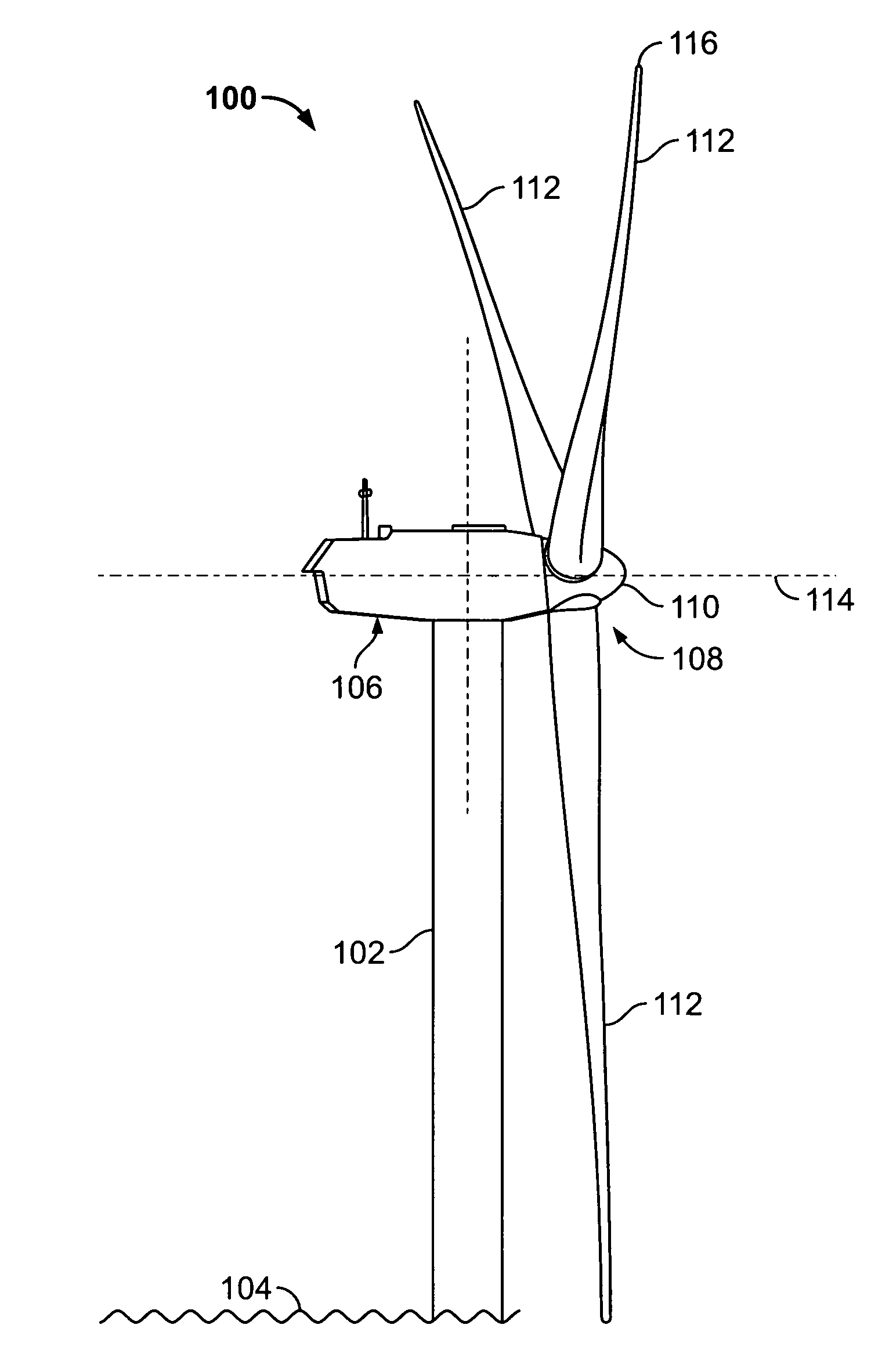
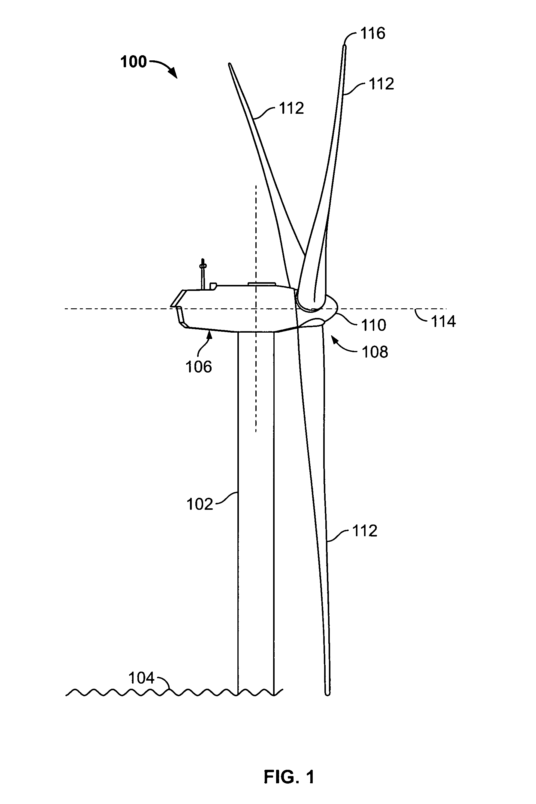
[0014]FIG. 1 is a schematic illustration of an exemplary wind turbine generator 100. In the exemplary embodiment, wind turbine generator 100 is a horizontal axis wind turbine. Alternatively, wind turbine 100 may be a vertical axis wind turbine. Wind turbine 100 has a tower 102 extending from a supporting surface 104, a nacelle 106 mounted on tower 102, and a rotor 108 coupled to nacelle 106. Rotor 108 has a rotatable hub 110 and a plurality of wind turbine blades, or rotor blades 112, coupled to hub 110. In the exemplary embodiment, rotor 108 has three rotor blades 112. In an alternative embodiment, rotor 108 may have more or less than three rotor blades 112. A center line 114 extends through nacelle 106 and hub 110. Each rotor blade 112 includes a tip 116. In the exemplary embodiment, tower 102 is fabricated from tubular steel and includes a cavity (not shown in FIG. 1) extending between supporting surface 104 and nacelle 106. In an alternative embodiment, tower 102 is a lattice to...


PUM

PropertyMeasurementUnit
lengthaaaaaaaaaa
lengthaaaaaaaaaa
distanceaaaaaaaaaa

Abstract

A method of assembling a wind turbine blade includes forming a preform pressure surface member and a preform suction surface member. The method also includes forming at least one of a leading edge and a trailing edge. One method of forming the leading edge or the trailing edge includes coupling a preform cap member to one of a portion of the preform pressure surface member and a portion of the preform suction surface member. At least a portion of one of the preform pressure surface member and the preform suction surface member overlap at least a portion of the preform bond cap member. Another method of forming the leading edge or the trailing edge includes coupling the preform pressure surface member to the preform suction surface member wherein at least a portion of the preform pressure surface member overlaps at least a portion of the preform suction surface member.

Description

BACKGROUND OF THE INVENTION[0001]This invention relates generally to rotary machines and more particularly, to methods and apparatus for fabricating wind turbine blades.[0002]Generally, a wind turbine generator includes a rotor having multiple blades. The rotor is sometimes mounted within a housing, or nacelle, that is positioned on top of a base, for example a truss or tubular tower. At least some known utility grade wind turbines (i.e., wind turbines designed to provide electrical power to a utility grid) can have rotor blades of 30 meters (m) (100 feet (ft)) or more in length.[0003]Many known wind turbine blades are generally difficult and time consuming to assemble. Some known methods of fabricating wind turbine blades include forming a plurality of members using resin transfer molding techniques. Such techniques typically include placing a preshaped fiber reinforcement preform into a closed molding of a similar shape, transferring a resin into the mold such that the resin impre...

Claims


Application Information

Patent Timeline
Patent Type & Authority Applications(United States)
IPC IPC(8): F03D9/00B29C65/54B29C65/72B32B38/00B29C65/00B23P15/04F01D5/14
CPCB29C70/845B29L2031/082B29L2031/085Y10T156/10F05B2230/50Y02E10/721Y10T29/49336F03D1/065Y02E10/72Y02P70/50
Inventor ALTHOFF, NICHOLAS KEANERIAHI, AMIRBILLEN, ANDREW JOHNBAKHUIS, JAN WILLEM
Owner GENERAL ELECTRIC CO
Learn More