Display apparatus

a technology of display apparatus and display screen, which is applied in the field of display screen, can solve the problems of difficult miniaturization and increased cost in comparison with ordinary display screen apparatus, and achieve the effect of improving the sn ratio of light receiving system and reducing the influence of nois

Active Publication Date: 2009-06-11
JAPAN DISPLAY WEST
View PDF18 Cites 45 Cited by
  • Summary
  • Abstract
  • Description
  • Claims
  • Application Information

AI Technical Summary

Benefits of technology

[0020]According to the present invention, the influence by noise can be reduced, and the SN ratio of the light receiving system can be improved without requiring a calibration operation when turning on the power.

Problems solved by technology

However, a display apparatus having coordinate input function means as described above, had the problems that miniaturization was difficult, and costs became higher in comparison with ordinary display apparatuses.

Method used


Image

  • Display apparatus
  • Display apparatus
  • Display apparatus

Examples


Embodiment Construction

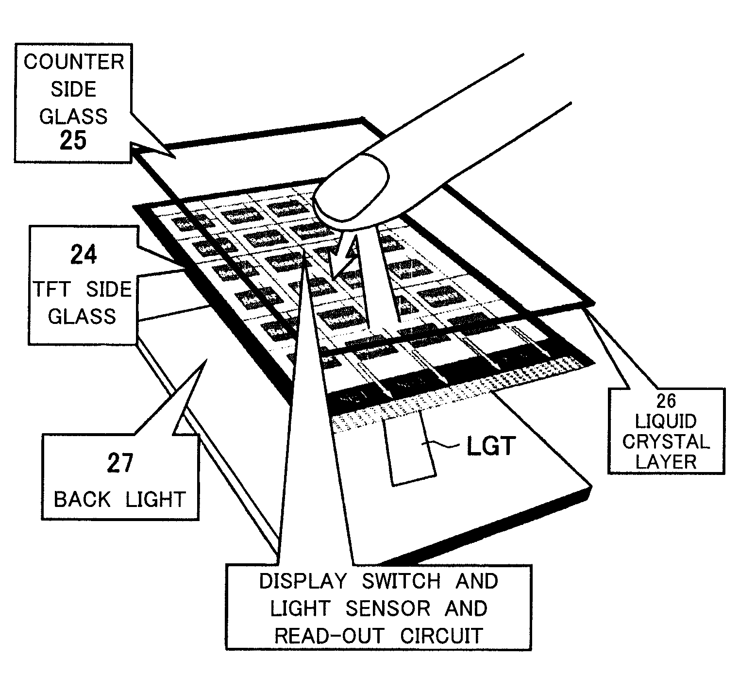
[0031]Below, an embodiment of the present invention will be explained with reference to the attached drawings.

[0032]In the following description, first, the basic configuration and functions of a liquid crystal image display apparatus providing a light receiving element for each display pixel will be explained for facilitating understanding, then an embodiment according to a concrete structure will be explained.

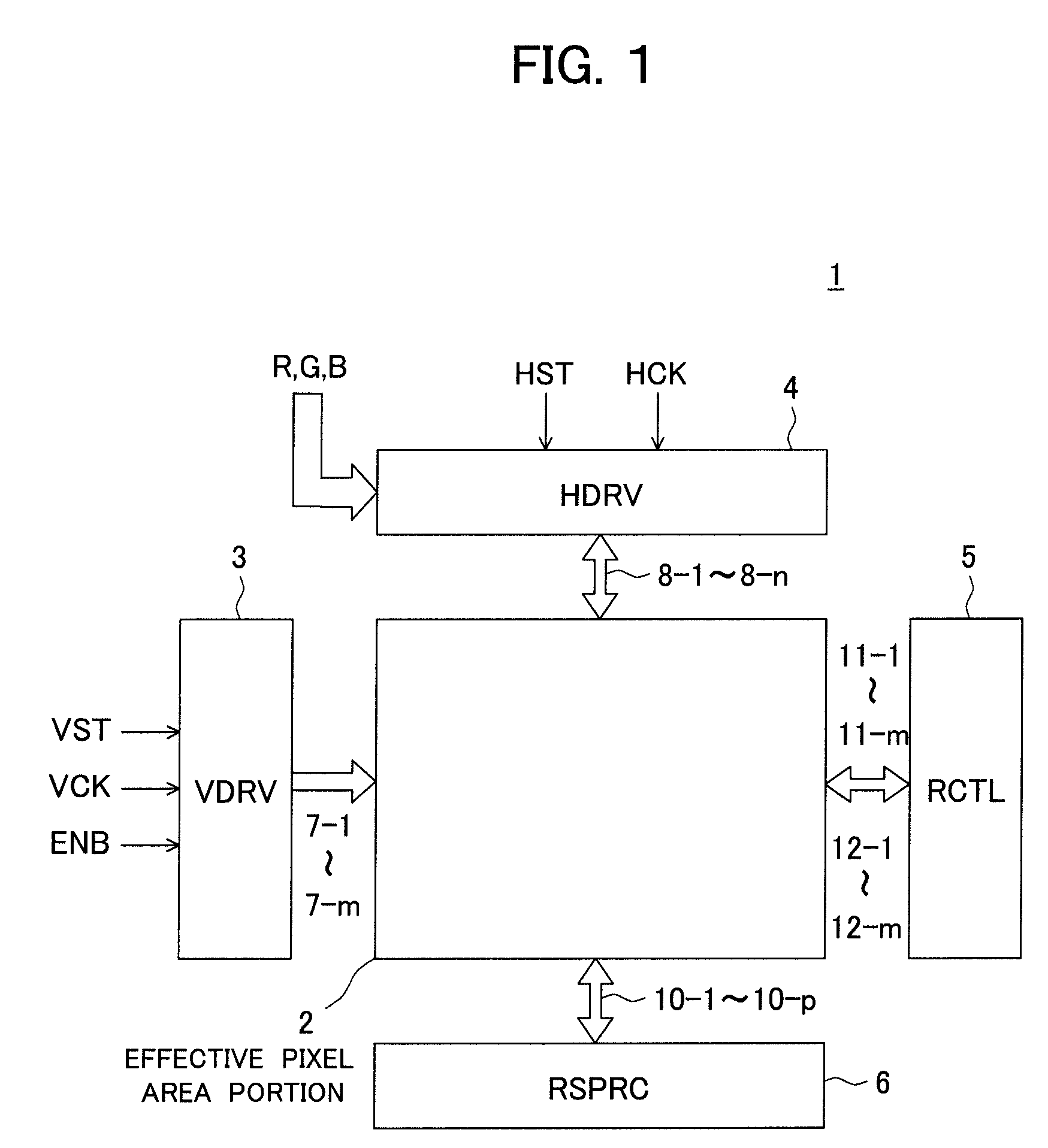
[0033]FIG. 1 is a block diagram showing an example of the configuration of a liquid crystal image display apparatus according to the embodiment of the present invention.

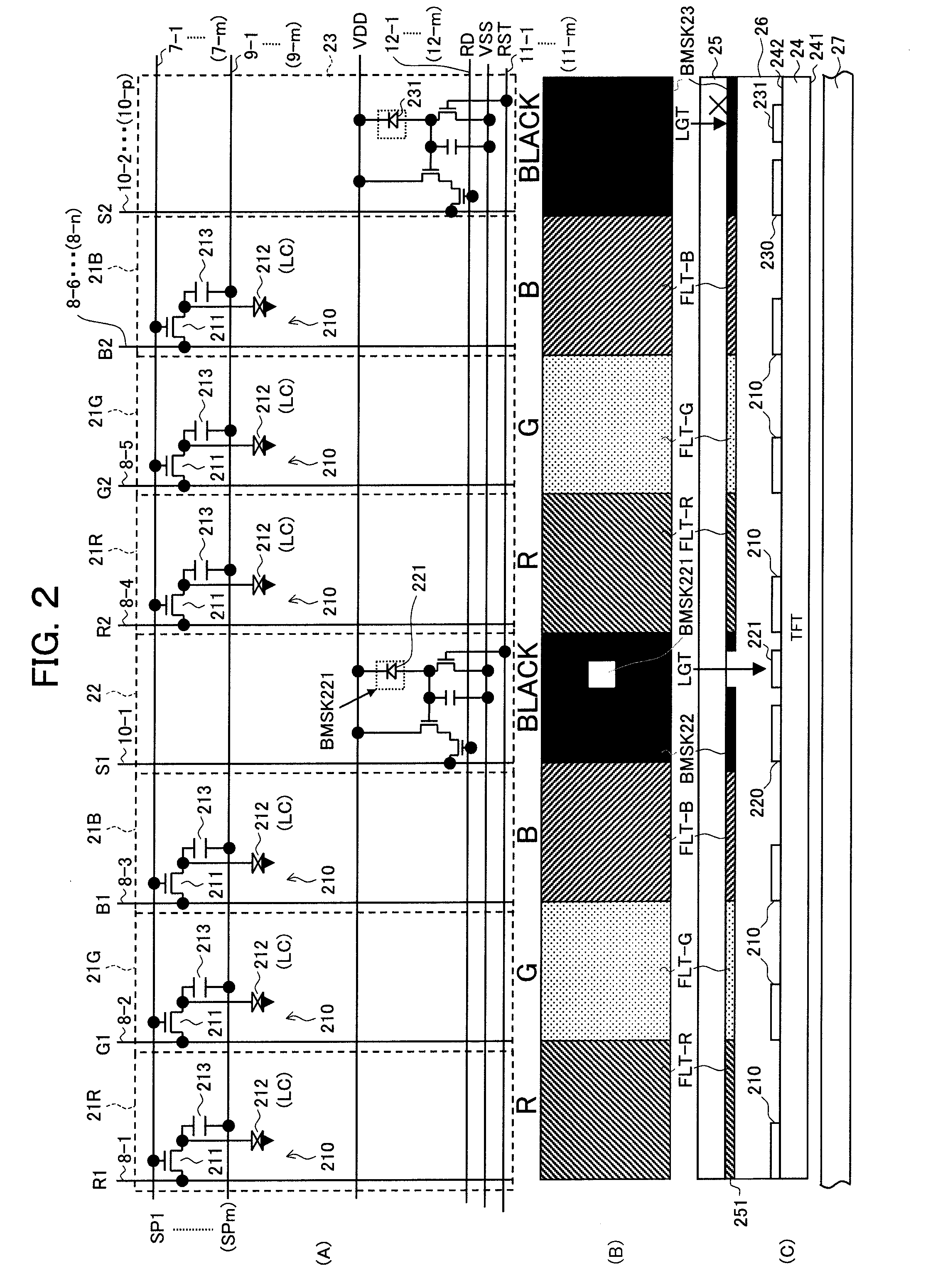
[0034]FIGS. 2(A) to 2(C) are diagrams showing a first example of the configuration of an effective pixel area portion in the liquid crystal image display apparatus of FIG. 1, in which FIG. 2(A) shows a matrix of cells, FIG. 2(B) shows a plan view, and FIG. 2(C) shows a sectional view.

[0035]A liquid crystal image display apparatus 1, as shown in FIG. 1, has an effective pixel area portion 2, vertical drive circ...


PUM

PropertyMeasurementUnit
areaaaaaaaaaaa
transparentaaaaaaaaaa
pressureaaaaaaaaaa

Abstract

A liquid crystal display apparatus having little influence of noise and able to improve an SN ratio of a light reception system without requiring a calibration operation when turning on the power, is provided. The apparatus has a plurality of display cells 21 having display circuits 210, light receiving cells 22 each including a light receiving element 221, a reference cell 23 having a configuration equivalent to the configuration of the light receiving cell and blocked from incidence of a light upon the light receiving element 221, and a received light signal processing circuit 6 performing differential signal processing of an output signal of the light receiving cell 22 and an output signal of the reference cell 23 and deleting noise.

Description

TECHNICAL FIELD[0001]The present invention relates to a display apparatus provided with a light receiving element in a display pixel portion or on a frame of the display pixel portion.BACKGROUND ART[0002]Several techniques providing coordinate input functions in display apparatuses themselves have been proposed.[0003]Specifically, for example, a display apparatus using a pressure sensitive type touch panel system (see, for example, Patent Documents 1 and 2) and a display apparatus using an electromagnetic induction type touch panel system (see, for example, Patent Document 3) are known.[0004]However, a display apparatus having coordinate input function means as described above, had the problems that miniaturization was difficult, and costs became higher in comparison with ordinary display apparatuses.[0005]Therefore, in recent years, there have been being actively developed display apparatuses for overcoming the above problem, in which a light receiving element is provided to each p...

Claims


Application Information

Patent Timeline
Patent Type & Authority Applications(United States)
IPC IPC(8): G02F1/133G06F3/042
CPCG02F1/13318G02F1/13338G02F1/133512H01L27/1214G06F3/0416G06F3/0421G02F1/13454G06F3/04182G02F1/1339G06F3/0418
Inventor NAKAJIMA, YOSHIHARUYAMANAKA, GO
Owner JAPAN DISPLAY WEST
Why Eureka
Try Eureka