Image forming apparatus and color deviation correcting method and program

a technology applied in the field of image forming apparatus and color deviation correcting method, can solve the problem of complex structure of optical units, and achieve the effect of flexibly coping with complex thermal shift characteristics, low color deviation, and high quality

Active Publication Date: 2009-06-11
CANON KK
View PDF3 Cites 13 Cited by
  • Summary
  • Abstract
  • Description
  • Claims
  • Application Information

AI Technical Summary

Benefits of technology

[0018]According to the invention, even when it is difficult to find out the correlation between an optical unit and its peripheral temperature change, a fluctuation of the laser beam irradiating position for the color deviation correction can be precisely predicted. That is, by using the invention, with respect to the color deviation caused by the fluctuation of the laser beam irradiating position, the color deviation correction can be realized irrespective of the presence or absence of a correlation between the intra-apparatus temperature and the color deviation fluctuation tendency. Thus, the high quality image creation with little color deviation can be realized.
[0019]Values of parameters which are applied to an algorithm are individually set every color and every operating mode, so that it is possible to flexibly cope with complicated thermal shift characteristics.

Problems solved by technology

Such an optical unit has a very complicated structure as compared with the structure in the related art.

Method used


Image

  • Image forming apparatus and color deviation correcting method and program
  • Image forming apparatus and color deviation correcting method and program
  • Image forming apparatus and color deviation correcting method and program

Examples


embodiment 1

[0045]the invention will now be described with reference to FIGS. 1 to 8B.

[0046]

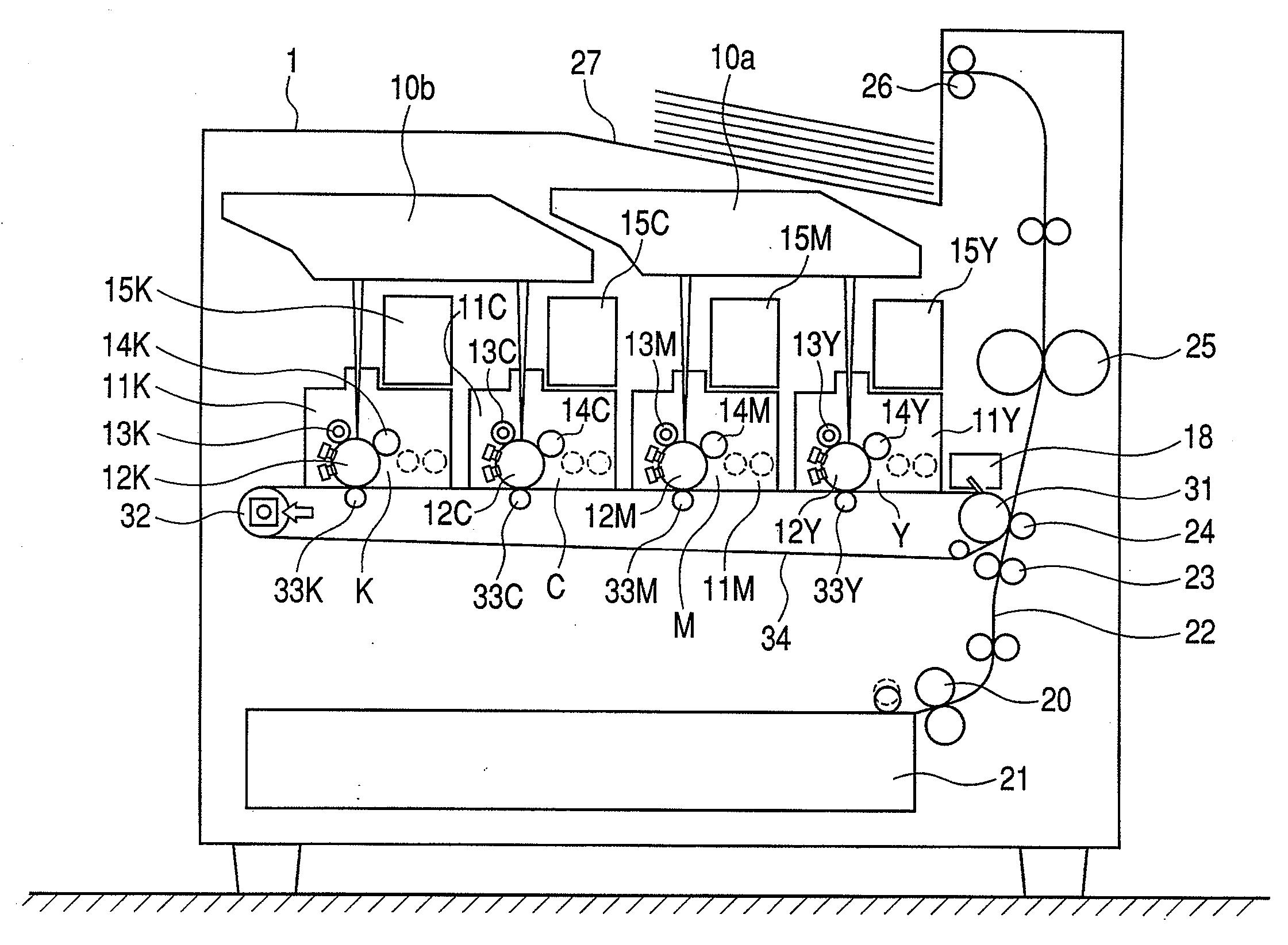
[0047]FIG. 1 is a schematic cross sectional view of an image forming apparatus to which the invention is applied. Engine portions for forming primary images of total four colors of yellow, magenta, cyan, and black (hereinbelow, abbreviated to Y, M, C, and K) are arranged in an upper portion of a printer main body 1.

[0048]Print data transmitted from an external apparatus such as a PC (personal computer) is received by a video controller for controlling the printer main body 1 and output as write image data to a laser scanner (optical unit) 10 corresponding to each color. The laser scanner 10 irradiates a laser beam onto photosensitive drums 12Y, 12M, 12C, and 12K (hereinbelow, reference numerals in which Y, M, C, and K are omitted are used in the case where it is unnecessary to particularly specify the color) and draws a light image according to the write image data. In the image forming apparatus of the ...

embodiment 2

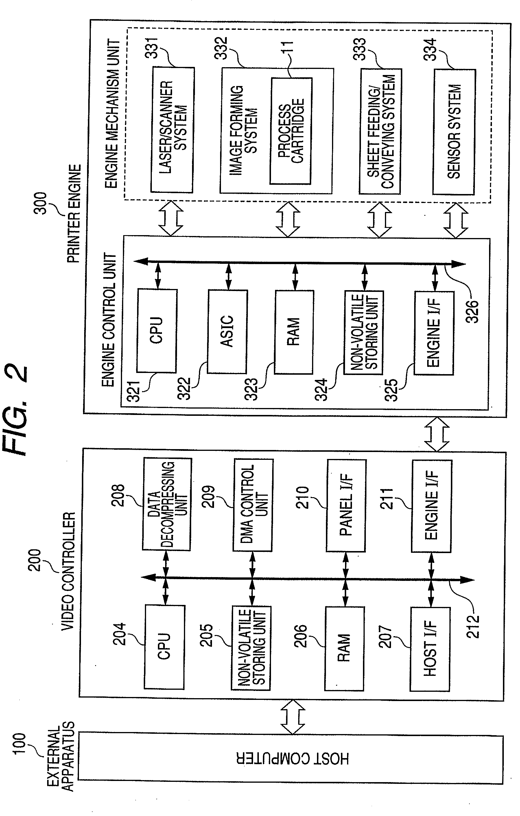
[0144]In the case of using the algorithm function (expression (3)) described in the embodiment 2, the information of the operating mode (m) as a parameter necessary for the arithmetic operation is received from the CPU 321 of the printer engine 300. The information of the input variable dT is received from the sensor system 334 including the sensor as an environment detecting unit. Those information is received through the engine I / F 325 and the engine I / F 211.

[0145]In the case where the CPU 204 of the video controller 200 executes the arithmetic operations, it is assumed that the parameter table (FIG. 5) has been stored in the non-volatile storing unit 205.

[0146]Also in the embodiment, even in the case where it is difficult to find out a correlation between the optical unit and its peripheral temperature change, the laser beam irradiating position fluctuation is predicted and the high image quality can be maintained.

embodiment 6

[0147]An embodiment 6 will now be described hereinbelow. The invention is not limited to the contents of the embodiments described above.

[0148]In the image forming apparatus of the embodiment, the laser scanner of such a system that the laser beams for two stations are scanned by one unit has been used. However, the invention can be applied irrespective of the construction of the laser scanner. The invention can be also arbitrarily applied to a construction in which a dedicated scanner unit is provided every station and to a construction in which the laser beams of four stations are scanned by one laser scanner unit.

[0149]Although the invention has been applied to the color deviation phenomenon in the sub-scanning direction in the above embodiments, the invention can be applied irrespective of the main scan or sub-scan. For example, in the case of applying the invention to a color deviation caused by a fluctuation in main scanning magnification, it is sufficient to form an algorithm...


PUM


Abstract

The invention has an image forming apparatus with a deviation amount calculator for obtaining, by an arithmetic operation, by an arithmetic operation, the deviation amount between the laser beam irradiating positions for each color, under the condition that the deviation amount increases gradually according to a time lapse in at least one of the plurality of operating modes, according with a further time lapse, the deviation amount between the laser beam irradiating positions for each color decreases gradually, and according with a further time lapse, the deviation amount between the laser beam irradiating positions for each color is converged.

Description

BACKGROUND OF THE INVENTION[0001]1. Field of the Invention[0002]The present invention relates to an image forming apparatus, a color deviation correcting method, and its program and, more particularly, to a mechanism for predicting a deviation amount regarding a laser beam irradiating position in an image forming apparatus.[0003]2. Description of the Related Art[0004]In an image forming apparatus for forming a color image by overlaying toner images of a plurality of colors, from a viewpoint of quality of a product, it is important that the image of each color is accurately printed at a predetermined position on a printed matter, that is, no color deviation occurs. There are various factors of the color deviation. As one of the factors which exert a large influence, there is a fluctuation in laser beam irradiating position on a photosensitive material which occurs in association with a thermal deformation of an optical unit.[0005]A description will be made with reference to a schemat...

Claims


Application Information

Patent Timeline
Patent Type & Authority Applications(United States)
IPC IPC(8): H04N1/60G06F3/12
CPCH04N1/00002H04N1/00015H04N1/00023H04N1/0005H04N1/00063H04N2201/04767H04N1/00082H04N1/047H04N1/2307H04N1/2346H04N1/506H04N1/00068
Inventor YANO, TAKASHIENOMOTO, HISASHI
Owner CANON KK
Why Eureka
Try Eureka