
Video multicast, such as layered video multicast for example, using relay devices defined by a channel quality parameter hierarchy

a relay device and channel quality parameter technology, applied in the field of wireless communication, can solve the problems of high packet loss ratio and higher bandwidth variation of wireless channels, difficulty in video multicast over wireless networks, and difficulty in defining wireless channels by bursty and location dependent errors, etc., to achieve better measurement of wireless channels and improve video information distribution.

Active Publication Date: 2009-06-11
POLYTECHNIC INSTITUTE OF NEW YORK UNIVERSITY
View PDF4 Cites 34 Cited by
  • Summary
  • Abstract
  • Description
  • Claims
  • Application Information

AI Technical Summary

Benefits of technology

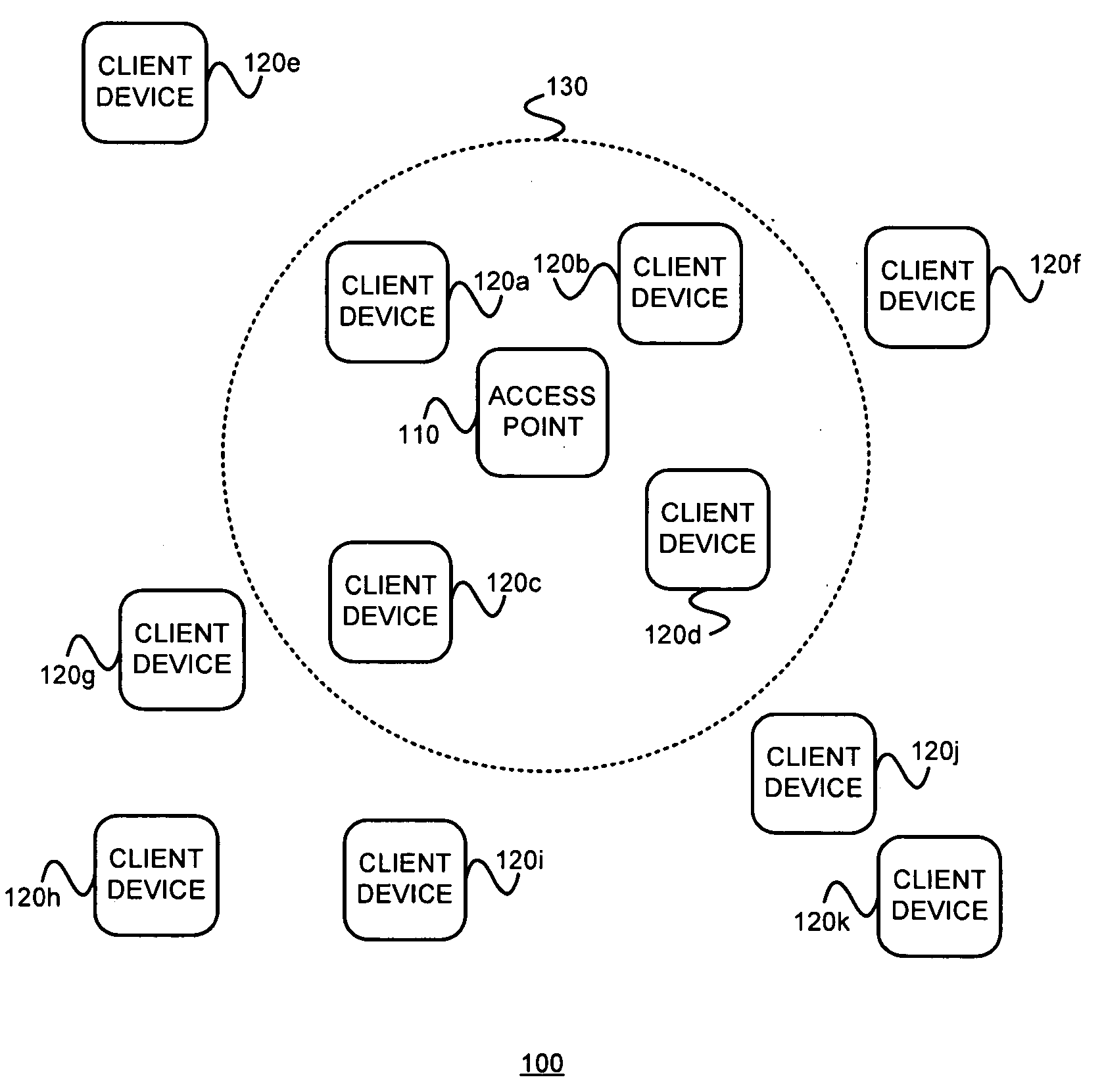
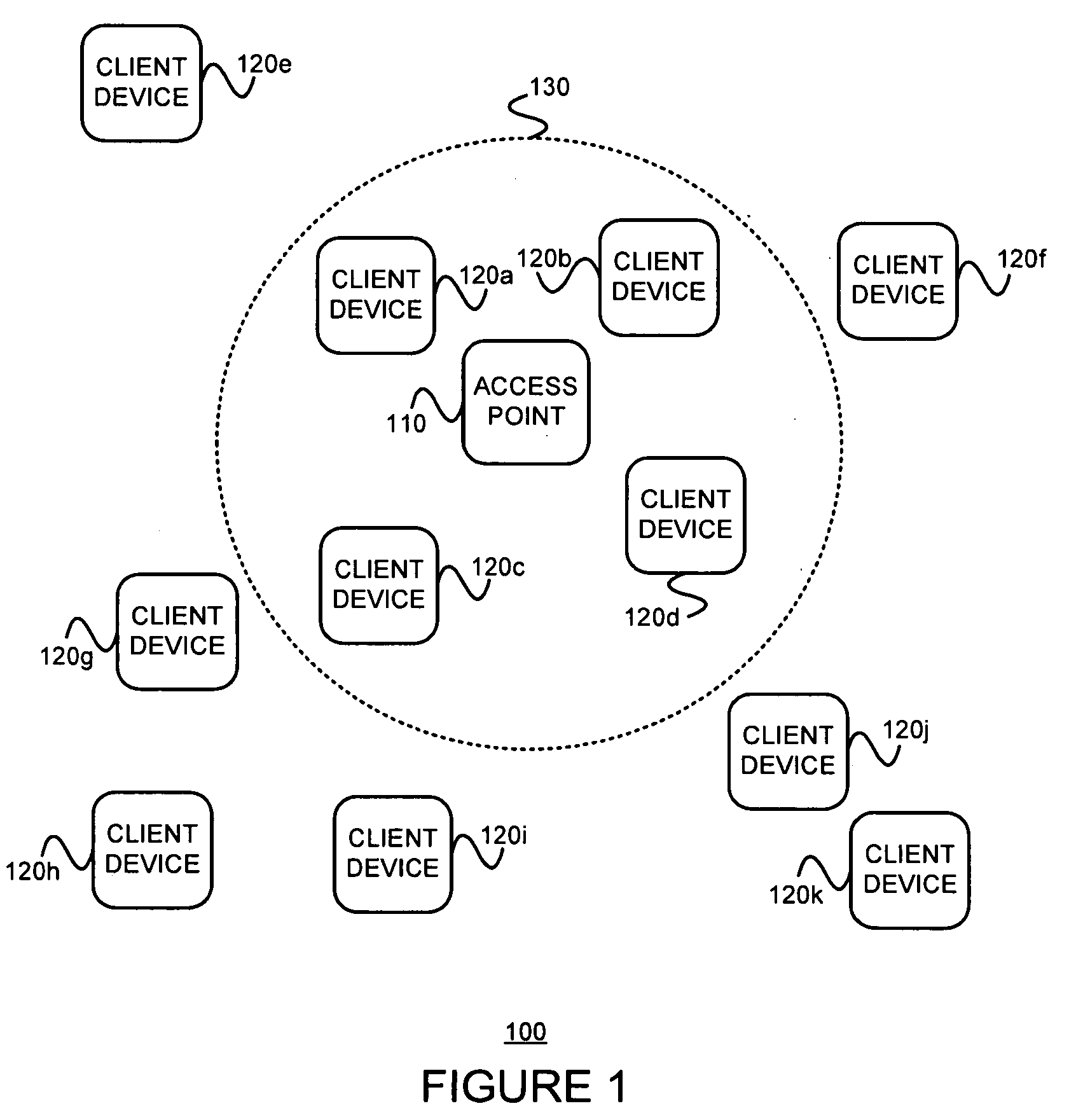
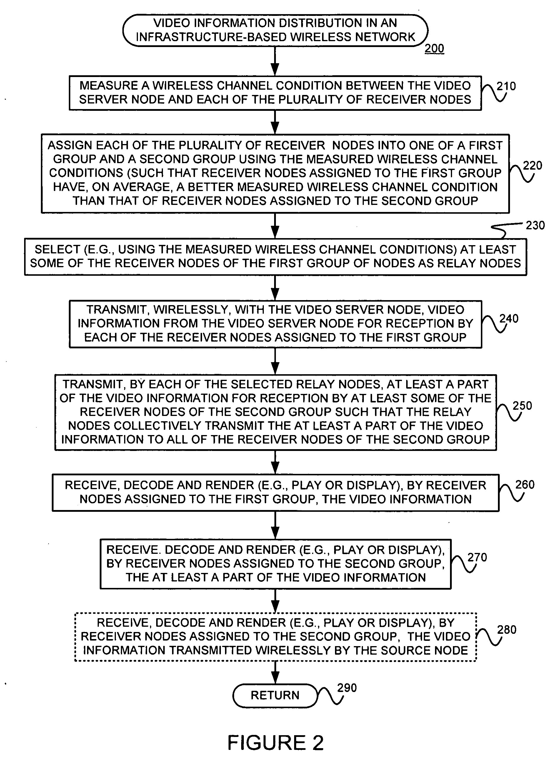
[0007]Exemplary embodiments consistent with the present invention may provide an improved distribution of video information in an infrastructure-based wireless network. Such exemplary embodiments may do so as follows. A wireless channel condition between the video server node and each of the plurality of receiver nodes is measured (or accepted, or otherwise determined). Each of the plurality of receiver nodes are assigned into one of a first group and a second group using the measured wireless channel conditions, wherein receiver nodes assigned to the first group have, on average (e.g., on average over time), a better measured wireless channel condition than that of receiver nodes assigned to the second group. At least some (e.g., one or more) of the receiver nodes of the first group of nodes are selected to serve as relay nodes. Video information (e.g., N layers) is then transmitted wirelessly from the video server node for ...

Problems solved by technology

Unfortunately, however, the use of heterogeneous receivers causes a higher packet loss ratio and higher bandwidth variations of wireless channels.
This makes video multicast over wireless networks challenging.
Wireless channels can be characterized by their bursty and location dependent errors.
Hence, each user in a multicast system will most likely lose different packets.
Although a simple Automatic Repeat reQuest (“ARQ”) based scheme is sometimes used to request lost packets, such a scheme is not a good solution for video multicast over wireless channels since it can cause a large volume of retransmissions.
However, none of these works consider the use of cooperation among receivers (e.g., nodes or client devices).
Consequently, all receivers of the system can be severely affected if even just one receiver is affected by path loss and multipath fading, or otherwise has poor channel conditions.

Method used


Image

  • Video multicast, such as layered video multicast for example, using relay devices defined by a channel quality parameter hierarchy
  • Video multicast, such as layered video multicast for example, using relay devices defined by a channel quality parameter hierarchy
  • Video multicast, such as layered video multicast for example, using relay devices defined by a channel quality parameter hierarchy

Examples


Embodiment Construction

[0015]The present invention may involve novel methods, apparatus, message formats, and / or data structures for improving video distribution, such as video distribution within an infrastructure-based wireless network for example. The following description is presented to enable one skilled in the art to make and use the invention, and is provided in the context of particular applications and their requirements. Thus, the following description of embodiments consistent with the present invention provides illustration and description, but is not intended to be exhaustive or to limit the present invention to the precise form disclosed. Various modifications to the disclosed embodiments will be apparent to those skilled in the art, and the general principles set forth below may be applied to other embodiments and applications. For example, although a series of acts may be described with reference to a flow diagram, the order of acts may differ in other implementations when the performance...


PUM


Abstract

Improved distribution of video information in an infrastructure-based wireless network is provided. A wireless channel condition between the video server node and each of the plurality of receiver nodes is measured (or accepted, or otherwise determined). Each of the plurality of receiver nodes are assigned into one of a first group and a second group using the measured wireless channel conditions, wherein receiver nodes assigned to the first group have, on average (e.g., on average over time), a better measured wireless channel condition than that of receiver nodes assigned to the second group. At least some (e.g., one or more) of the receiver nodes of the first group of nodes are selected to serve as relay nodes. Video information (e.g., N layers) is then transmitted wirelessly from the video server node for reception by each of the receiver nodes assigned to the first group. Each of the selected relay nodes then transmit at least a part (e.g., M≦N layers) of the video information for reception by at least some of the receiver nodes of the second group such that the relay nodes collectively transmit the at least a part of the video information to all of the receiver nodes of the second group. Receiver nodes assigned to the first group receive, decode and render the received video information. Similarly, receiver nodes assigned to the second group, receive, decode and render the received at least a part of the video information. The receiver nodes assigned to the second group may also use the (1) video information transmitted wirelessly by the source node and / or (2) copies of the at least a part of the video information transmitted by other relay nodes (that is, relay nodes not assigned to it), to the extent such information is received.

Description

§ 0. PRIORITY CLAIM[0001]This application claims the benefit of U.S. Provisional Patent Application Ser. No. 60 / 991,887 (incorporated herein by reference and referred to as “the '887 provisional”), titled “LAYERED VIDEO MULTICAST USING RELAYS” filed on Dec. 3, 2007, and listing Ozgu ALAY, Elza ERKIP, Thanasis KORAKIS, Shivendra S. PANWAR and Yao WANG as the inventors. The present invention is not limited to requirements of the particular embodiments described in the '887 provisional.§ 1. BACKGROUND OF THE INVENTION§ 1.1. Field of the Invention[0002]The present invention concerns wireless communications. In particular, the present invention concerns wireless distribution of video content.§ 1.2. Background Information[0003]In recent years, the demand for video applications over wireless networks has risen with the increase in both the bandwidth of wireless channels and the computational power of mobile devices. To provide efficient delivery among a group of users simultaneously, multi...

Claims


Application Information

Patent Timeline
IPC IPC(8): H04W4/00H04N7/173
CPCH04B5/0031H04B5/02H04B5/0062H04B5/77H04B5/72H04B5/48
Inventor ALAY, OZGUERKIP, ELZAKORAKIS, THANASISPANWAR, SHIVENDRA S.WANG, YAO
Owner POLYTECHNIC INSTITUTE OF NEW YORK UNIVERSITY
Learn More