Skew Compensation Across Polarized Optical Channels

a polarized optical channel and skew compensation technology, applied in the field of frame alignment and skew compensation across polarized optical channels, can solve the problems of skew between polarized channels, errors may be generated, and the reconstruction of 100 gigabit ethernet signals becomes more difficult, so as to achieve more efficient and accurate alignment and skew compensation.

Active Publication Date: 2009-06-11
INFINERA CORP
View PDF9 Cites 35 Cited by
  • Summary
  • Abstract
  • Description
  • Claims
  • Application Information

AI Technical Summary

Benefits of technology

[0015]Embodiments of the present invention provide systems, devices and methods for managing skew within a polarized multi-channel optical transport system. In a dual polarization QPSK system (hereinafter, “DP-QPSK system”), skew between polarized channels is compensated within the transport system by adding latency to at least one of the polarized channels. The amount of added latency may depend on various factors including the skew tolerance of the transport system and the amount of skew across the channels without compensation. This latency may be added optically or electrically, and at various locations on a channel signal path within a transport node. Additionally, various embodiments of the invention provide for novel methods of inserting frame alignment bit sequences within the transport frame overhead so that alignment and skew compensation may be more efficiently and accurately performed at the transport receiver.

Problems solved by technology

If this timing becomes too large (i.e., the signal skew is too large), then reconstruction of the 100 gigabit Ethernet signal becomes more difficult and errors may be generated in this process.
Skew between polarized channels may result from a number of factors relating to both the transmission medium and transport nodes.
Polarization modal dispersion (hereinafter, “PMD”) may cause differential latency between the channels during transport because of differing propagation velocities of the channels.
This difference in channel velocities results in a skewing of the timing between the channels.
Skew between polarized channels may also result in differences in signal path lengths between the channels.
One cause of these slight differences in lengths is variations of fiber pigtails lengths that propagate the polarized channels.
These different fiber pigtail lengths may also result in skewing between channels.
Other components, both optical and electrical, within a transport node may also introduce skew between these polarized channels.
As the client signal rate increases, the management of the skew may become more complex because of the relatively larger amount of data that is propagated through the transport network.
In either scenario, maintaining the timing relationship of this client data as it propagates through the transport network becomes more complex.

Method used


Image

  • Skew Compensation Across Polarized Optical Channels
  • Skew Compensation Across Polarized Optical Channels
  • Skew Compensation Across Polarized Optical Channels

Examples


Embodiment Construction

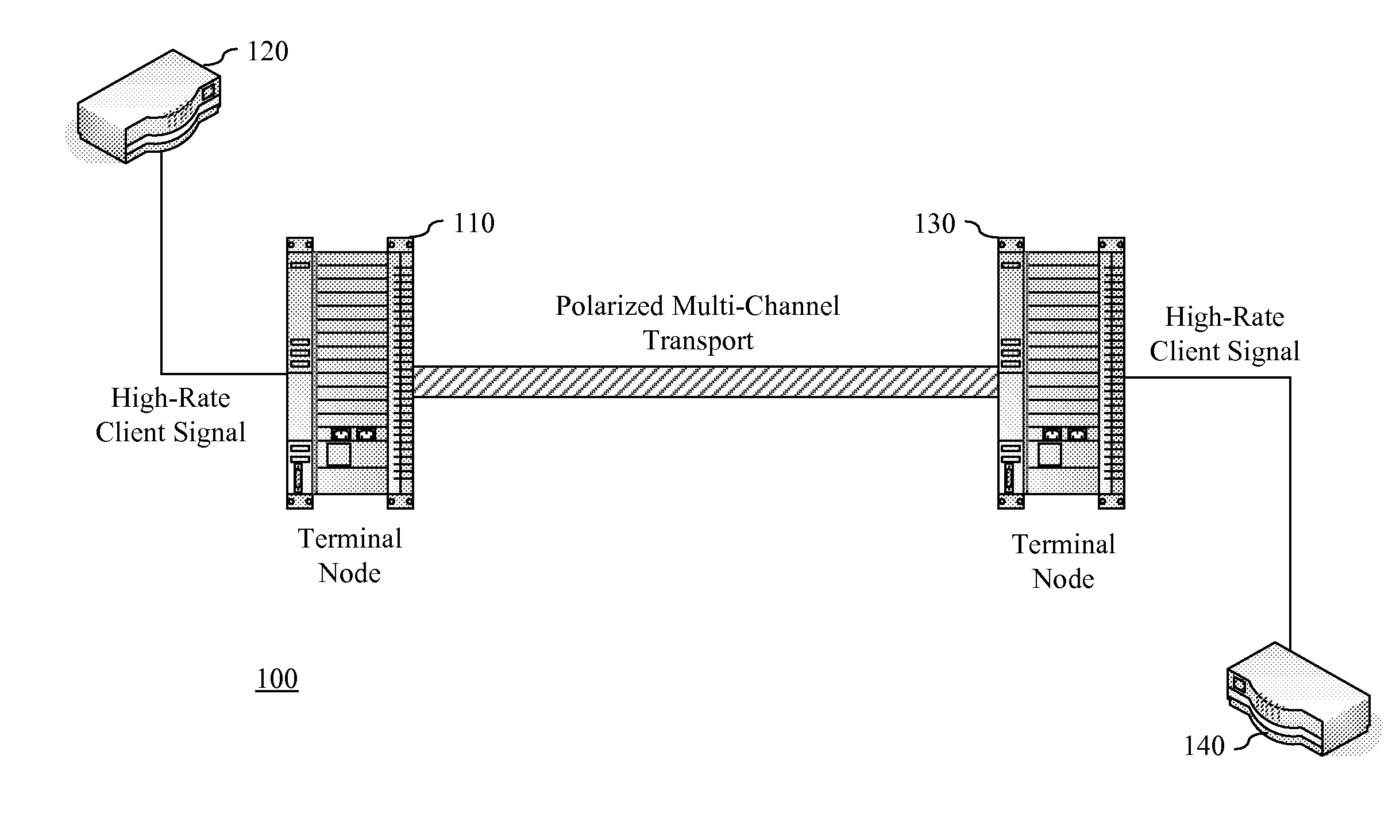
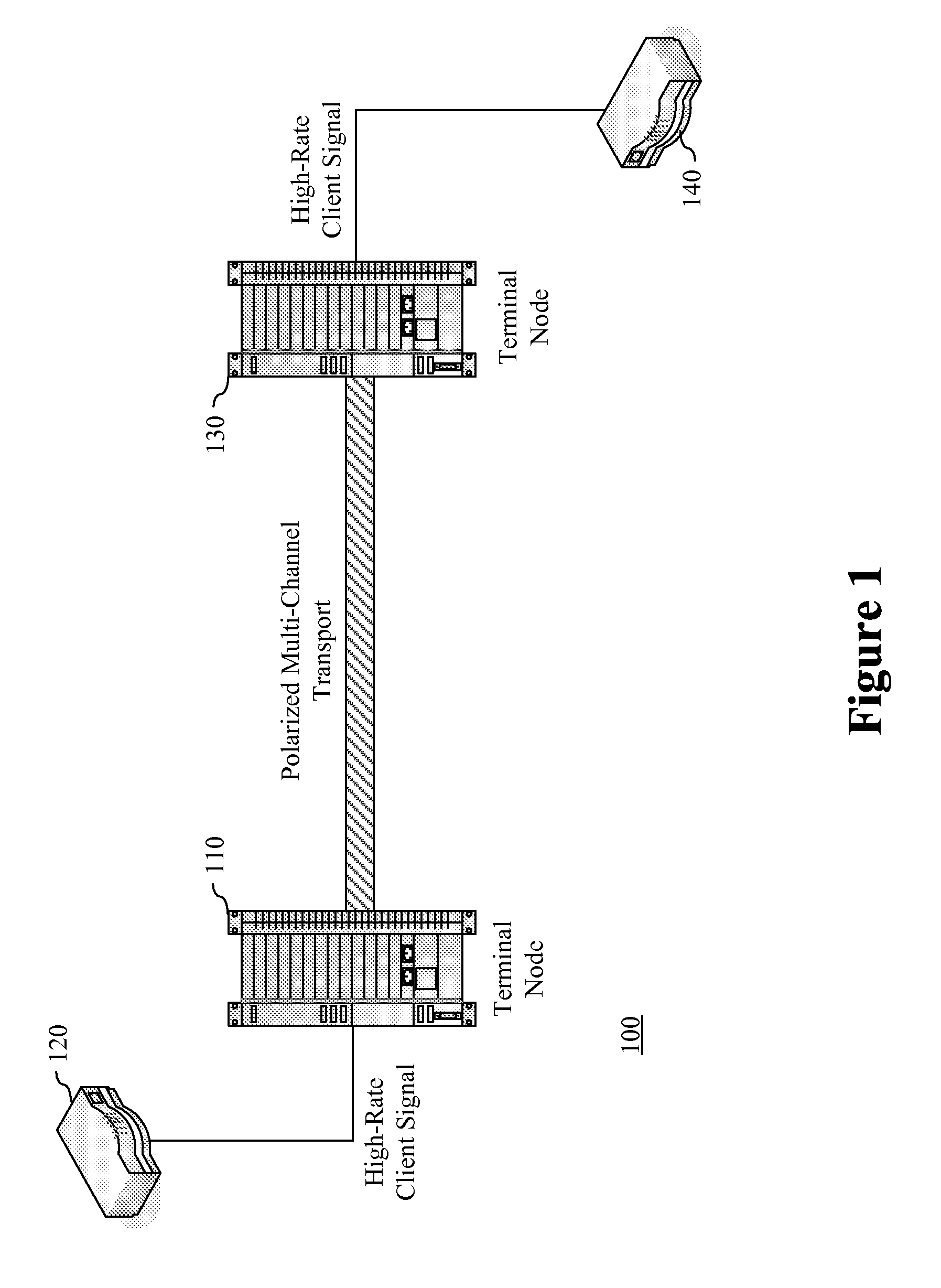
[0036]Embodiments of the present invention provide systems, devices and methods for managing skew within a polarized multi-channel optical transport system. In a DP-QPSK system, skew between polarized channels is compensated within the transport system by adding latency to at least one of the polarized channels. The amount of added latency may depend on various factors including the skew tolerance of the transport system and the amount of skew across the channels without compensation. This latency may be added optically or electrically, and at various locations on a channel signal path within a transport node, such as a terminal transmitter or receiver. Additionally, various embodiments of the invention provide for novel methods of inserting frame alignment bit sequences within the transport frame overhead so that alignment and skew compensation may be more efficiently and accurately performed at the transport receiver.

[0037]In the following description, for purpose of explanation, ...


PUM


Abstract

Embodiments of the present invention provide systems, devices and methods for managing skew within a polarized multi-channel optical transport system. In a DP-QPSK system, skew between polarized channels is compensated within the transport system by adding latency to at least one of the polarized channels. The amount of added latency may depend on various factors including the skew tolerance of the transport system and the amount of skew across the channels without compensation. This latency may be added optically or electrically, and at various locations on a channel signal path within a transport node, such as a terminal transmitter or receiver. Additionally, various embodiments of the invention provide for novel methods of inserting frame alignment bit sequences within the transport frame overhead so that alignment and skew compensation may be more efficiently and accurately performed at the transport receiver.

Description

BACKGROUND[0001]A. Technical Field[0002]The present invention relates generally to the management of skew within a polarized multi-channel optical system, and more particularly, to frame alignment and skew compensation across polarized optical channels within an optical transport system.[0003]B. Background of the Invention[0004]The capacity of transport systems is continually increasing to provide larger amounts of available bandwidth to clients. These transport systems are able to communicate large amounts of data using optical networking technologies. In certain systems, wavelength division multiplexed (hereinafter, “WDM”) transport systems communicate this data on multiple wavelengths between terminal nodes. These WDM systems offer a network provider scalable bandwidth without having to significantly expand the physical infrastructure of a network to realize this additional bandwidth.[0005]Certain transport systems are designed to receive a client signal, re-format the client sig...

Claims


Application Information

Patent Timeline
Patent Type & Authority Applications(United States)
IPC IPC(8): H04B10/00
CPCH04B10/5053H04B10/5057H04B10/697H04B10/676H04B10/532
Inventor PERKINS, DREW D.
Owner INFINERA CORP
Why Eureka
Try Eureka