Linear compressor with permanent magnets

a technology of permanent magnets and compressors, which is applied in the direction of piston pumps, positive displacement liquid engines, free piston pumps, etc., can solve the problems of reducing the power density, complex design of compressors, and limited application of this type of compressors, so as to save the length, improve the operation performance, and the effect of compact pumping assembly

Inactive Publication Date: 2009-06-11
IND TECH RES INST
View PDF14 Cites 5 Cited by
  • Summary
  • Abstract
  • Description
  • Claims
  • Application Information

AI Technical Summary

Benefits of technology

[0009]The present brushless and linear design has fewer elements and better operation performance. In addition, the movable cylinder ass

Problems solved by technology

The application of this kind of compressor is limited.
Moreover, the design of

Method used


Image

  • Linear compressor with permanent magnets
  • Linear compressor with permanent magnets
  • Linear compressor with permanent magnets

Examples


Embodiment Construction

[0022]The brushless linear compressor with permanent magnets of the present invention will be described in detail in accordance with the following preferred embodiments and accompanying drawings.

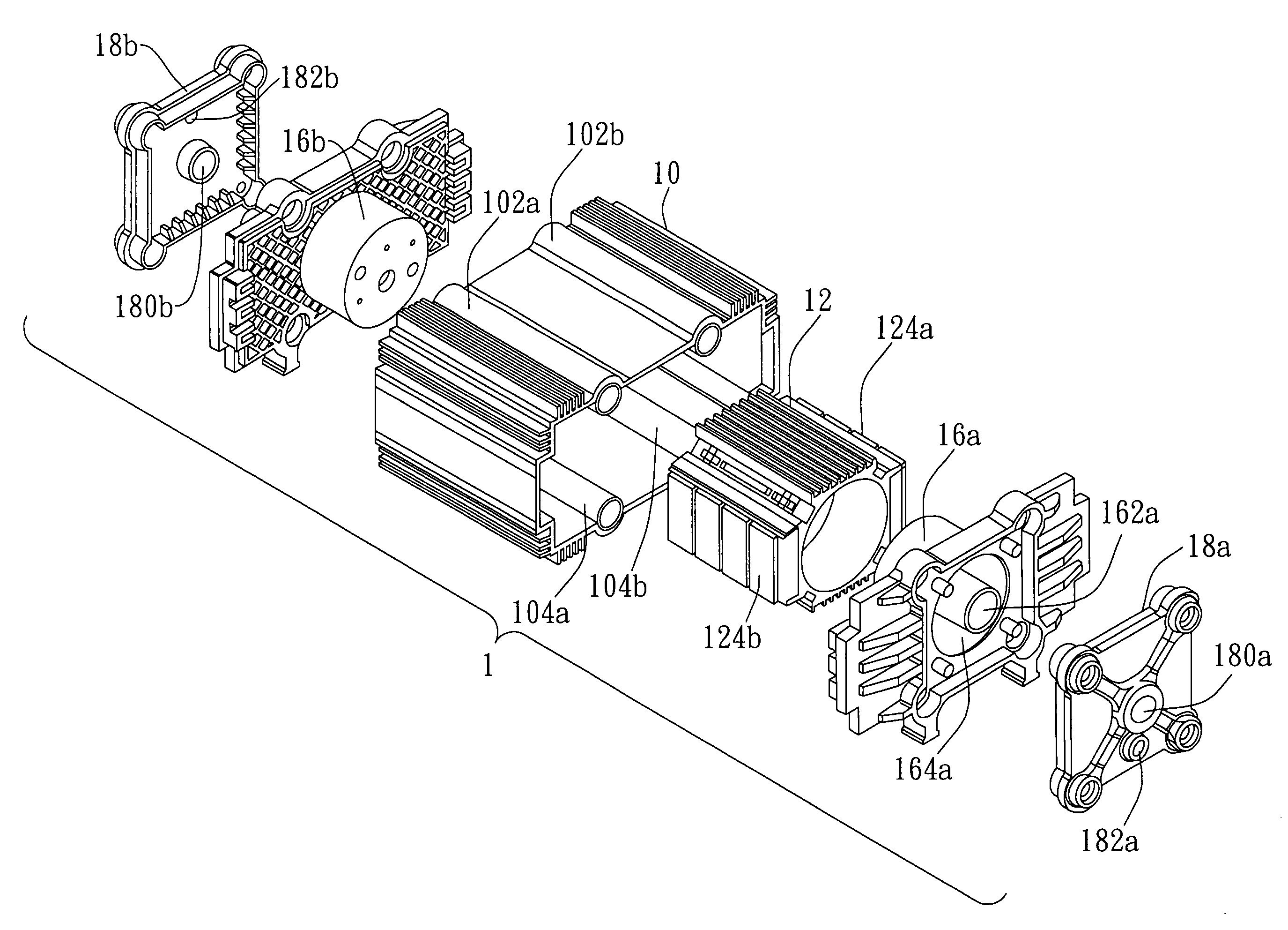
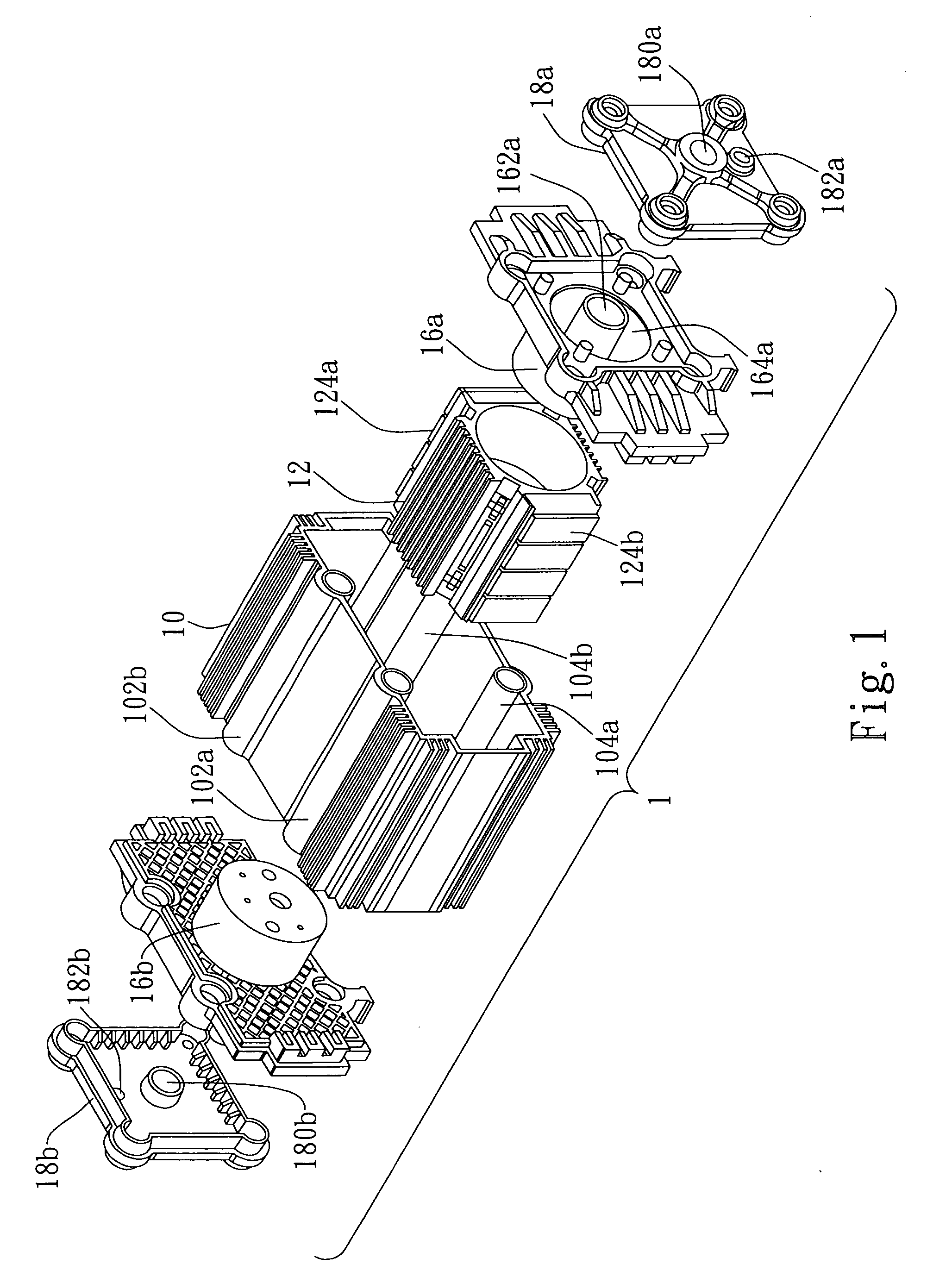
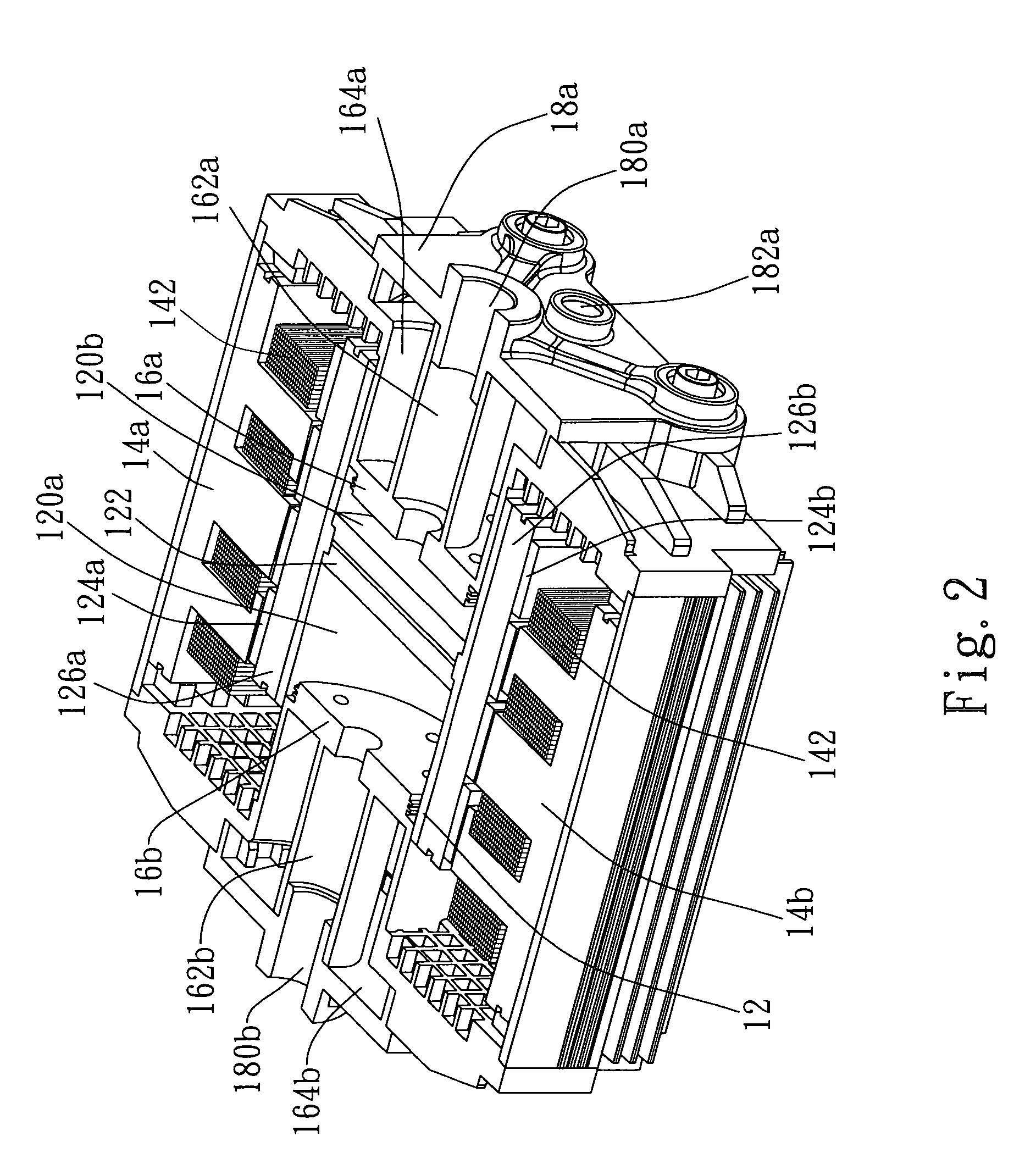
[0023]FIG. 1 is an exploded view of the brushless linear compressor with permanent magnets according to a first preferred embodiment of the present invention. FIG. 2 is a perspective view of the brushless linear compressor with permanent magnets of FIG. 1 after assembled. FIGS. 3A to 3C are perspective views of the brushless linear compressor with permanent magnets under different displacement of the movable cylinder. FIGS. 4A to 4C are schematic cross-sectional views of the primary structure of the brushless linear compressor with permanent magnets under different displacement of the movable cylinder corresponding to FIGS. 3A to 3C, respectively. According to the first preferred embodiment in FIG. 1, the brushless linear compressor with permanent magnets 1 mainly includes an outer shell 10,...


PUM


Abstract

This invention provides a compressor with brushless single-phase linear motor, which includes a movable cylinder associated with a permanent magnet array, at least a stationary electromagnetic winding set and a pair of stationary pistons. A partition plate is disposed in the movable cylinder to form a first sub-cylinder and a second sub-cylinder. The front ends of the pair of the stationary pistons are respectively placed in either of two openings of the movable cylinder at its two ends. An alternate current applied to the stationary electromagnetic winding set to generate alternately attracting/repelling forces to the permanent magnet array. The movable cylinder is hence alternately pushed forward and backward. The volumes of the first and second sub-cylinders are changed to compress air in the first sub-cylinder or the second sub-cylinder.

Description

BACKGROUND OF THE INVENTION[0001]1. Field of the Invention[0002]The present invention relates to the field of mechanical devices for the pumping of fluids which are powered by a brushless linear motor with permanent magnets.[0003]2. Description of the Related Art[0004]The oxygen therapeutic devices include oxygen concentrator, compressing oxygen bottle, oxygen regulator, liquefied oxygen, flow regulator etc. Oxygen therapeutic devices are primarily used for chronic obstructive pulmonary disease, oxygen supply during sleep and hypoxemia. The patients can be classified into mobile and immobile. 80% patients need oxygen for 1.5 to 2.0 liter per minute and for 15 hours every day. The mobile patients may need portable and stationary oxygen devices in their daily life. When they do exercise, the demanded oxygen flow rate is increased to 4˜6 liters per minute. The oxygen concentrator extracts oxygen from air, whose key elements is therapeutic-level compressor, which requires advanced techn...

Claims


Application Information

Patent Timeline
IPC IPC(8): F04B31/00
CPCF04B35/045
Inventor SHEN, TE-YANGCHEN, CHUNG-CHU
Owner IND TECH RES INST
Why Eureka
Try Eureka