Guide Bar Arrangement

a technology of guide bars and spherical bars, which is applied in the direction of chain saws, metal sawing accessories, manufacturing tools, etc., can solve the problems of impaired oil supply to the saw chain, achieve excellent lubrication of the saw chain, reduce the degree of soiling, and reduce the free flow cross-sectional area

Inactive Publication Date: 2009-06-18
ANDREAS STIHL AG & CO KG
View PDF7 Cites 3 Cited by
  • Summary
  • Abstract
  • Description
  • Claims
  • Application Information

AI Technical Summary

Benefits of technology

[0007]It can be provided that the insert has several individual bores. Guide bars are usually produced by a stamping process. The manufacture of several small bores is not possible by means of a stamping process because stamping does not allow for the production of arbitrarily small structures. The insert can be manufactured in a simple way. In this connection, it can be provided, for example, that the insert is made from plastic material and is produced by an injection-molding process. Also, the manufacture from metal or ceramic material can be advantageous. It can also be advantageous that the insert has a grid-like structure. The insert can then be cut or stamped in a simple way from the grid-like material. In order to achieve very many, very fine passages, it can be provided that the insert comprises a wiremesh that is provided with passages. In this connection, the wiremesh can be in particular comprised of a multi-layer configuration. In the fabric structures openings are formed as a result of the woven structure itself and they provide non-uniform passages.
[0008]It is provided that the insert has at least one bore whose longitudinal center axis is positioned relative to the exterior side of the guide bar at an angle of less than 90°. It has been found that by slantedly arranging an oil supply opening a reduced degree of soiling is achieved. The slantedly positioned bore can be produced in the insert in a simple way, for example, when the insert is made from plastic material, by an injection molding process. Also, machining of an insert from metal can be advantageous. It is provided that the longitudinal center axis of the bore is positioned relative to the exterior side of the guide bar at an angle that is approximately from 15° to approximately 45°. Expediently, the bore is also inclined in the longitudinal direction of the guide bar. For this purpose, it is in particular provided that the longitudinal center axis of the bore is positioned relative to the longitudinal center axis of the guide bar at an angle that is approximately from 30° to approximately 60°. The angle at which the longitudinal center axis of the bore is positioned relative to the longitudinal center axis of the guide bar can be changed in a simple way by changing the orientation of the insert in the opening. The opening is designed in this context in particular so as to match the drive projection of the drive link.
[0009]The insert can be secured in a simple way in the opening in that the insert is press-fit into the opening. However, it is also possible to employ different kinds of attachment of the insert, for example, by welding, soldering, gluing of the like. Advantageously, the insert is comprised at least partially of ceramic material. In this connection, a ceramic coating of the insert can be provided. It has been found that ceramic material has a minimal tendency to become soiled so that deposits of dirt are prevented by the ceramic material.
[0010]Advantageously, the area of the second sidewall of the guide bar that is opposite the opening is of a closed configuration. The guide bar therefore has an oil supply opening only on one longitudinal side, i.e., on the longitudinal side resting against the housing of a motor chain saw where an oil supply channel of a lubricant oil pump opens. The longitudinal center axis of the opening is advantageously positioned approximately perpendicularly to the exterior side of the guide bar. Accordingly, the opening can be produced in a simple way by a stamping method or by drilling or milling.
[0011]An excellent lubrication of the saw chain is achieved when the oil supply opening opens into the guide groove above the groove base and in an area where the drive links of the saw chain glide. In this way, the oil exiting from the insert can be entrained directly by the drive links. As a result of the reduced free flow cross-sectional area an oil film is formed on the surface of the insert across which oil film the drive links glide and entrain oil. In this way it is prevented that oil will run directly into the groove base and therefore cannot contribute to lubrication of the saw chain. In order to further improve the lubrication of the saw chain, it is provided that in the area of the opening at the base of the groove a raised portion is arranged that projects into the area across which the drive links of the saw chain will glide in operation.
[0012]Advantageously, the opening for supply of oil is designed as an oil bore. An oil bore, i.e., an oil supply opening with a round cross-section can be produced in a simple way.

Problems solved by technology

Such oil bores can become clogged in operation by chips or the like so that the oil supply to the saw chain is impaired.

Method used


Image

  • Guide Bar Arrangement
  • Guide Bar Arrangement
  • Guide Bar Arrangement

Examples


Embodiment Construction

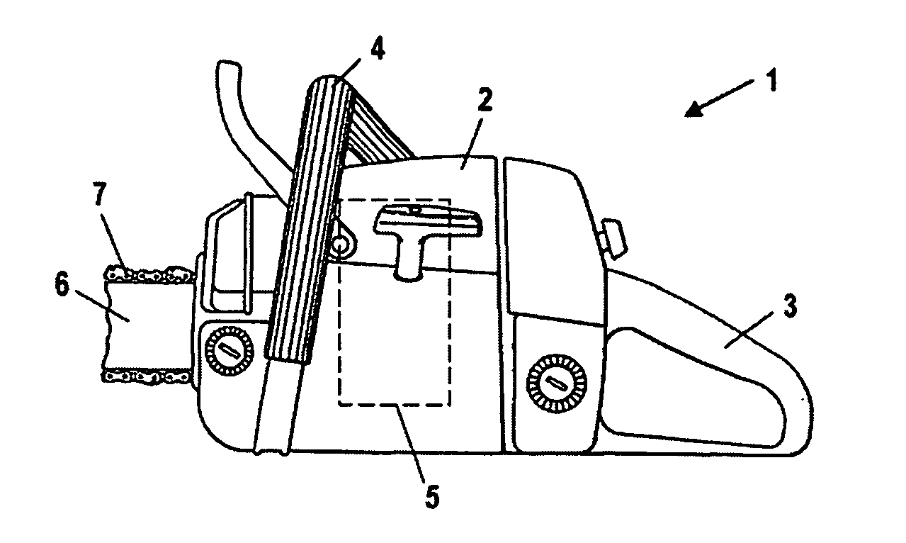
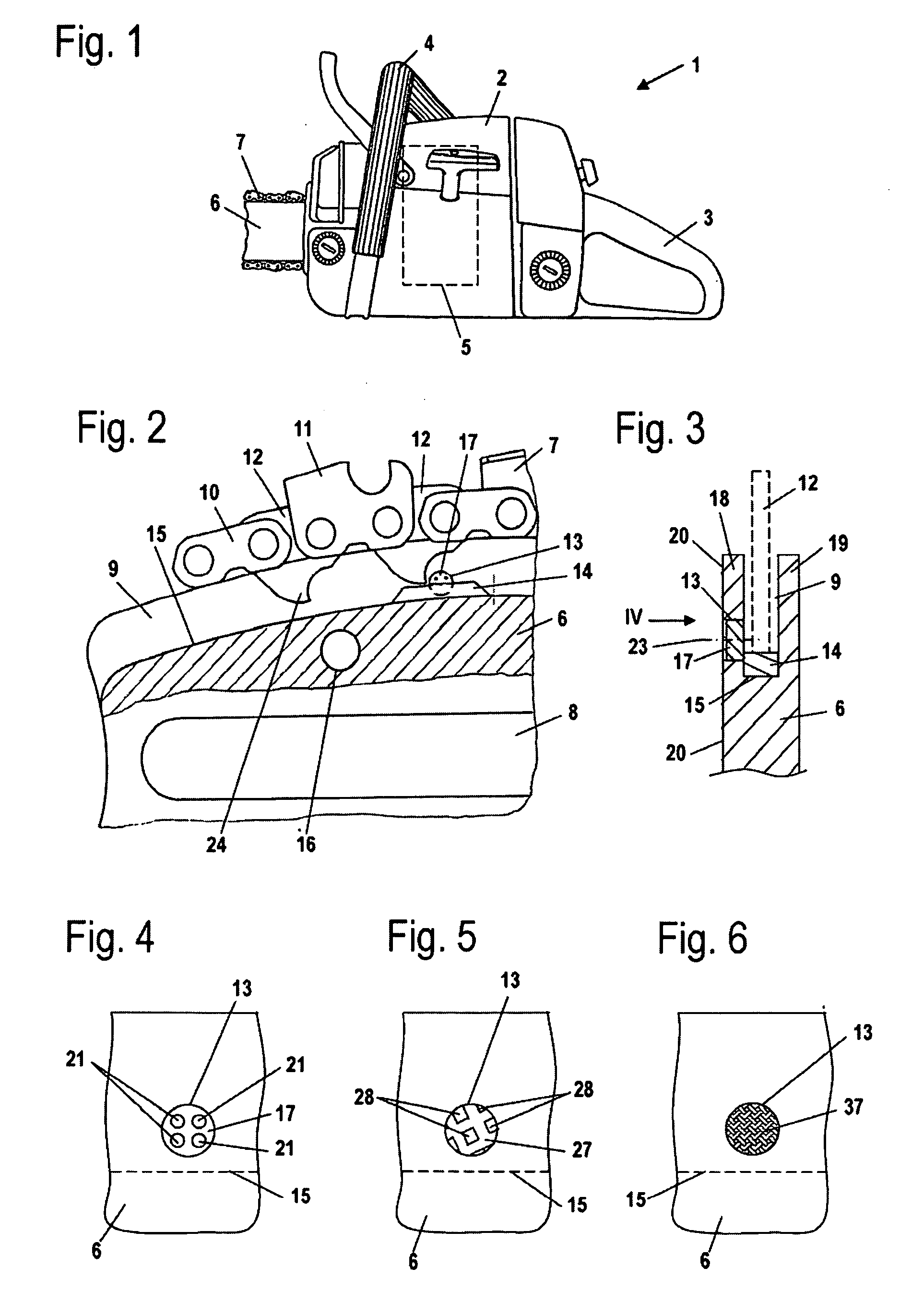
[0024]As an embodiment for a motor chain saw, FIG. 1 shows a hand-guided, hand-carried motor chain saw 1. The invention is however also useable in connection with other motor chain saws, for example, pole pruners or plantation harvesting machines, so-called harvesters.

[0025]The motor chain saw 1 has a housing 2 on which a rear handle 3 as well as a grip pipe 4 are secured. On the end of the housing 2 opposite the rear handle 3 a guide bar 6 projects forwardly and a saw chain 7 is arranged thereon peripherally. In the housing 2 a drive motor 5 is arranged that drives the saw chain 7 in circulation about the guide bar 6.

[0026]In FIG. 2 the area of the guide bar 6 secured to the motor chain saw 1 is shown in section. For fixation on the motor chain saw 1 the guide bar 6 has a longitudinal groove 8 as well as transverse bores 16 of which one is shown in FIG. 2. A tensioning device (not shown) for the saw chain 7 can engage the transverse bore 16. The guide bar 6 has at its outer circumf...


PUM

PropertyMeasurementUnit
angleaaaaaaaaaa
angleaaaaaaaaaa
angleaaaaaaaaaa

Abstract

A guide bar arrangement has a guide bar having a guide groove that extends about an outer circumference of the guide bar. A saw chain is driven in circulation in the guide groove about the guide bar. The guide groove is delimited by a groove base, a first sidewall and a second sidewall positioned opposite the first sidewall. The guide bar has an opening for supply of oil into the guide groove, wherein the opening extends from an exterior side of the guide bar, wherein the exterior side extends in a longitudinal direction of the guide bar, into the guide groove and opens in the first sidewall into the guide groove. An insert is secured in the opening and reduces a free flow cross-sectional area of the opening.

Description

BACKGROUND OF THE INVENTION[0001]The invention concerns a guide bar arrangement comprising a guide bar and a saw chain driven in circulation, wherein the guide bar has a guide groove that extends about the outer circumference of the guide bar and in which the saw chain is guided. The guide groove is delimited by a groove base and two oppositely positioned sidewalls. The guide bar has an opening for supply of oil that extends from an exterior side of the guide bar, extending in the longitudinal direction of the guide bar, into the guide groove and that opens in a first sidewall into the guide groove.[0002]U.S. Pat. No. 4,211,007 discloses a guide bar that has two oppositely positioned oil bores. The oil bores are arranged in the sidewalls of the guide groove. Such oil bores can become clogged in operation by chips or the like so that the oil supply to the saw chain is impaired.SUMMARY OF THE INVENTION[0003]It is an object of the invention to provide a guide bar arrangement of the afo...

Claims


Application Information

Patent Timeline
Patent Type & Authority Applications(United States)
IPC IPC(8): B27B17/04
CPCB27B17/12
Inventor GALSTER, WERNER
Owner ANDREAS STIHL AG & CO KG
Why Eureka
Try Eureka