Power transmission apparatus for vehicle

a technology for transmission apparatus and vehicle, applied in the direction of electric propulsion mounting, machine/engine, gear shifting, etc., can solve the problems of giving a sense of discomfort to occupants and following inconvenience, and achieve the effect of suppressing smooth shifting of gears, and effective suppression of the occurrence of shift shock

Inactive Publication Date: 2009-06-18
TOYOTA JIDOSHA KK
View PDF4 Cites 26 Cited by
  • Summary
  • Abstract
  • Description
  • Claims
  • Application Information

AI Technical Summary

Benefits of technology

[0015]The power transmission apparatus according to the fourth aspect of the invention includes: the first shift unit; the second shift unit; at least one electric motor that is connected to the rotating element of the first shift unit or the rotating element of the second shift unit so that the rotational speed of the electric motor is changed in accordance with the gear-shift of the first shift unit or the gear-shift of the second shift unit; and the control unit that restricts, during the gear-shift of one of the first shift unit and the second shift unit, completion of the inertia phase of the gear-shift of the other of the first shift unit and the second shift unit with the use of the electric motor, when the gear-shift of the first shift unit and the gear-shift of the second shift unit are performed at the same time and the gear ratio of the first shift unit and the gear ratio of the second shift unit are changed in the opposite directions. When the gear-shift of the first shift unit and the gear-shift of the second shift unit are performed at the same time, the gear-shift of one of the first shift unit and the second shift unit is started and completed in the period from when the gear-shift of the other of the first shift unit and the second shift unit is started until when the gear-shift of the other of the first shift unit and the second shift unit is completed. Accordingly, it is possible to suppress occurrence of shift shock, thereby shifting gears smoothly. That is, it is possible to provide the power transmission apparatus for a vehicle with which occurrence of shift shock is effectively suppressed.

Problems solved by technology

In the process of their studies, the following inconvenience was found.
Such fluctuations may give a sense of discomfort to occupants.

Method used


Image

  • Power transmission apparatus for vehicle
  • Power transmission apparatus for vehicle
  • Power transmission apparatus for vehicle

Examples


first embodiment

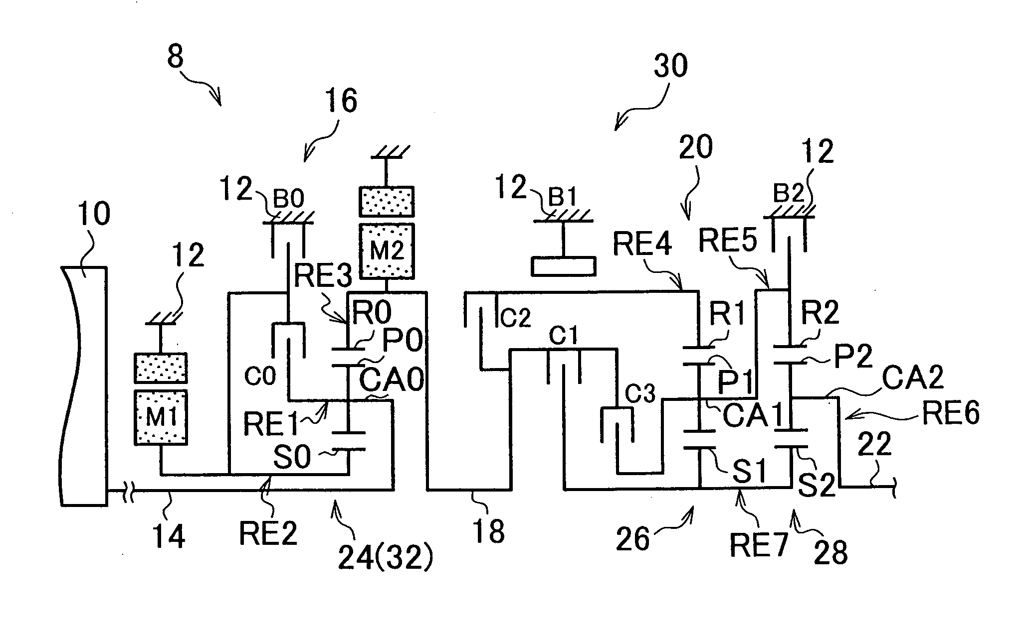
[0031]The engine 10 is a main drive power source that generates drive power used to drive the vehicle, and is formed of an internal combustion engine, for example, a gasoline engine or a diesel engine, or an external combustion engine. As shown in FIG. 1, in the power transmission apparatus 8 according to the invention, the engine 10 and the first shift unit 16 are directly connected to each other. That is, the engine 10 is connected to the first shift unit 16 without provision of a fluid transmission device such as a torque converter or a fluid coupling between the engine 10 and the first shift unit 16. Therefore, for example, when the engine 10 is connected to the first shift unit 16 via, for example, the above-mentioned pulsation absorbing damper, it is regarded that the engine 10 is directly connected to the first shift unit 16. Because the configuration of the power transmission apparatus 8 is symmetric with respect to the axis thereof, the lower portion of the power transmissi...

second embodiment

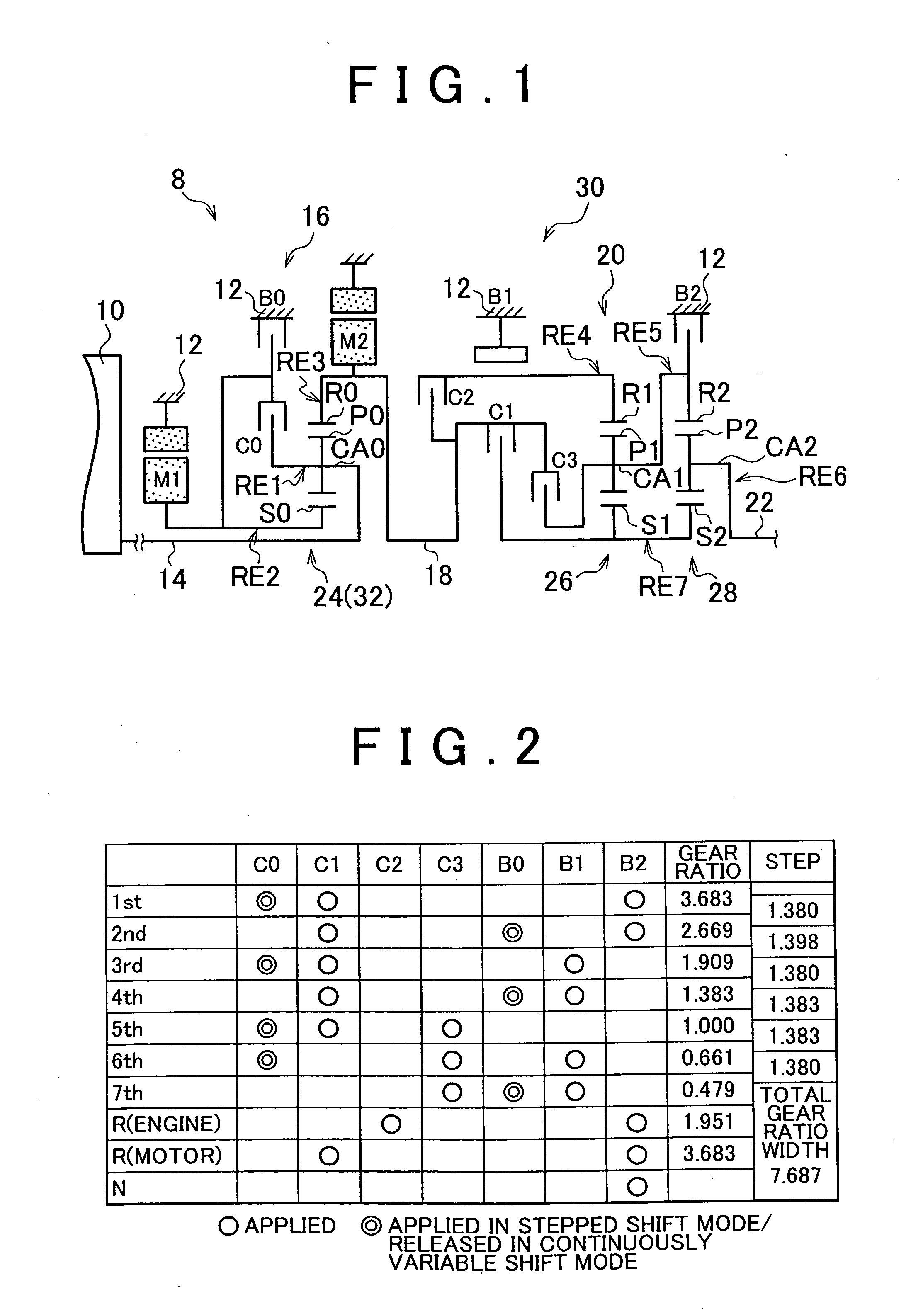
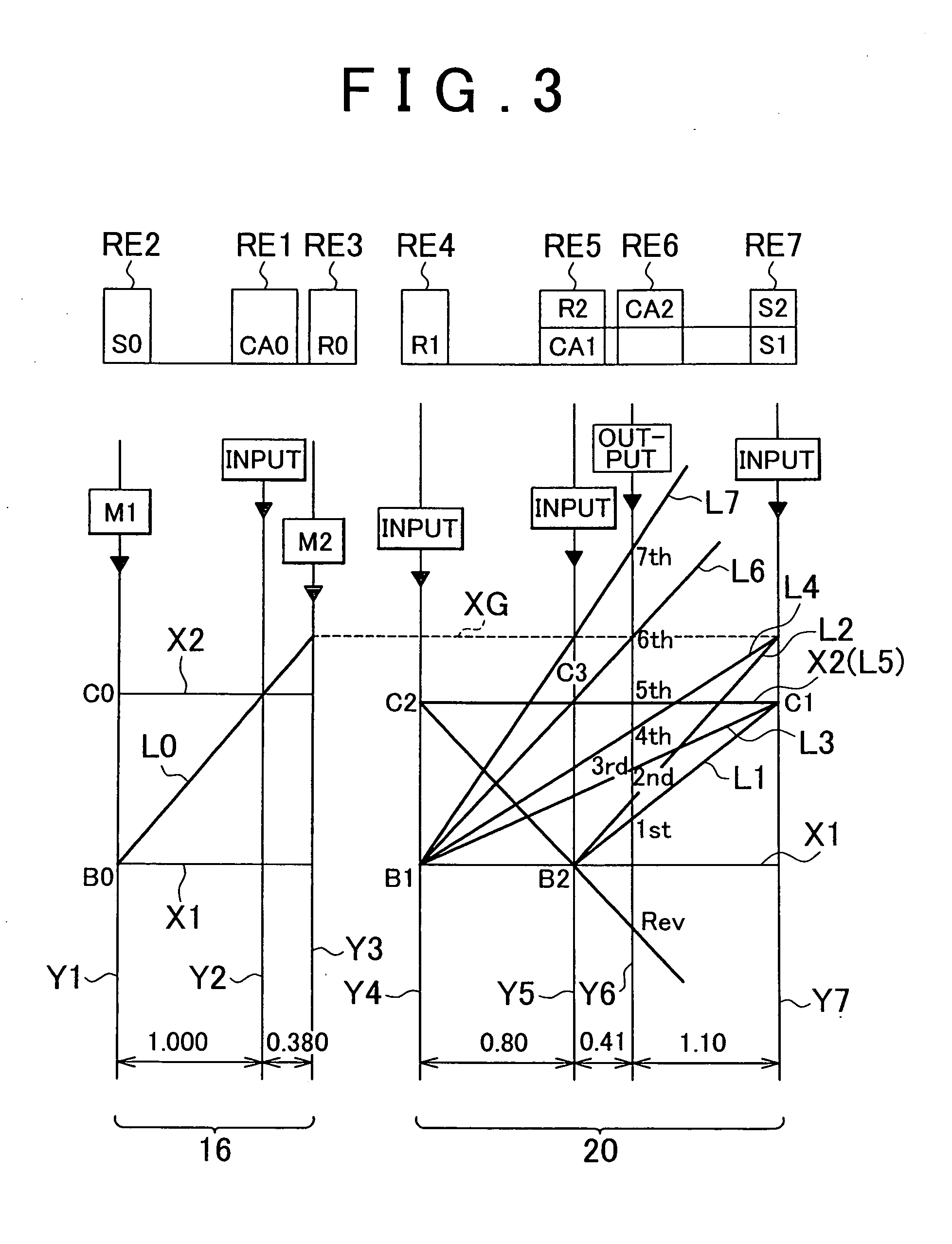
[0110]FIG. 10 is a view schematically showing the structure of a vehicle power transmission apparatus 90 according to the invention. FIG. 11 is an operation chart showing the relationship between shift operations, which are performed when a transmission of the power transmission apparatus 90 in FIG. 10 is made to shift gears in a stepped manner, and the combinations of hydraulic friction application devices that are applied when the shift operations are performed. FIG. 12 is a collinear diagram illustrating the relative rotational speed in each gear when the transmission of the power transmission apparatus 90 in FIG. 10 is made to shift gears in a stepped manner.

[0111]As shown in FIG. 10, the power transmission apparatus 90 according to the second embodiment of the invention includes the first shift unit 16 which has the same structure as that in the first embodiment of the invention and in which the first electric motor M1, the power split mechanism 32 and the second electric motor...


PUM


Abstract

A power transmission apparatus for a vehicle includes: a first shift unit; a second shift unit; an electric motor connected to a rotating element of the first shift unit or the second shift unit so that the rotational speed changes in accordance with a gear-shift of the first shift unit or the second shift unit; and a control unit that controls at least one of start timings of inertia phases of the gear-shifts of the first and second shift units using the electric motor, when the gear-shifts of the first and second shift units are performed simultaneously and gear ratios of the first and second shift units are changed in opposite directions. With this control, in the simultaneous gear-shift, the gear-shift of one of the shift units is started and completed in a period from start of the gear-shift of the other shift unit until completion of this gear-shift.

Description

INCORPORATION BY REFERENCE[0001]The disclosure of Japanese Patent Application No. 2007-326399 filed on Dec. 18, 2007 including the specification, drawings and abstract is incorporated herein by reference in its entirety.BACKGROUND OF THE INVENTION[0002]1. Field of the Invention[0003]The invention relates generally to a power transmission apparatus for a vehicle, which includes a first shift unit, a second shift unit, at least one electric motor that is connected to a rotating element of the first shift unit or a rotating element of the second shift unit so that the rotational speed of the electric motor changes in accordance with a gear-shift of the first shift unit or a gear-shift of the second shift unit, and a control unit. More specifically, the invention relates to refinements in the technology for suppressing occurrence of shift shock.[0004]2. Description of the Related Art[0005]There is a power transmission apparatus for a vehicle, which includes a first shift unit, a second ...

Claims


Application Information

Patent Timeline
Patent Type & Authority Applications(United States)
IPC IPC(8): F16H59/04B60K6/445B60K6/547B60L50/16B60W10/06B60W10/08B60W10/10B60W20/00F02D29/00F02D29/02F16H59/68F16H61/08F16H61/68F16H61/684F16H61/686F16H63/40F16H63/50
CPCB60K1/02Y10T74/19251B60K6/445B60K6/547B60L2240/421B60L2240/441B60L2240/445B60L2240/486B60W10/06B60W10/115B60W20/00B60W2510/0638B60W2510/0676B60W2510/0685B60W2510/081B60W2510/1015B60W2520/10B60W2520/105B60W2520/28B60W2540/10B60W2540/12B60W2710/0605F16H3/728F16H2037/0873F16H2061/0451F16H2200/0056F16H2200/201F16H2200/2048F16H2306/22Y02T10/642Y02T10/6239B60K6/365Y02T10/62Y02T10/64B60W20/30
Inventor TABATA, ATSUSHIKUMAZAKI, KENTAMATSUBARA, TOORU
Owner TOYOTA JIDOSHA KK
Why Eureka
Try Eureka