Supercharge Your Innovation With Domain-Expert AI Agents!

Munition or projectile for battlefield illumination

a projectile and battlefield technology, applied in the direction of projectiles, ammunition projectiles, weapons, etc., can solve the problems of increased fire danger, increased danger to persons and the environment, and regular risk of pyrotechnic materials, so as to avoid undesired blinding and sufficient illumination

Inactive Publication Date: 2009-06-18
RHEINMETALL WAFFE MUNITION GMBH
View PDF15 Cites 10 Cited by
  • Summary
  • Abstract
  • Description
  • Claims
  • Application Information

AI Technical Summary

Benefits of technology

[0012]The invention is likewise based on the idea of placing several flare bodies in a projectile or body of a projectile, where the systems for reducing the rate of descent or the brake systems (such as parachutes, etc.) are made ready to operate by a delay element only after a predetermined flight time and after stabilization. In this regard, it is intended that it be possible to select different delay times for the ignition of the individual flare bodies. The flare bodies can be placed in all types of containers or bodies, such as the bodies of artillery shells. Filler pieces between the flare bodies are to be adapted to the flare bodies and possibly the number of flare bodies as well. The filler pieces or filler elements preferably form a central ignition channel for the ignition of the flare bodies. Due to the eccentric arrangement of the flare bodies inside the projectile bodies, the flare bodies are dispersed far more favorably after their expulsion than previously known systems with a single flare body or multiple flare bodies. This has the further result that the flare bodies are not struck or damaged as much by the base of the projectile.
[0013]The form of the flare bodies also makes it possible for them to serve as modules for different projectiles. As a result of the distribution of several flare bodies at several levels in the projectile, better illumination is produced by the simultaneously shining flare bodies.
[0014]If the flare bodies are integrated in two or more levels inside the projectile, it makes sense, for example, to vary the delay times of the flare bodies of the different levels. Due to the fact that different delay times can be set, the flare bodies then start to shine at different times. The advantage associated with this is that, when the different delay times are coordinated, the total period of illumination can be increased. In the event of a malfunction of a system for reducing the rate of descent or in the event of an ignition failure, the other flare bodies continue to be functional.
[0015]The integration of several flare bodies has the further advantage that, due to the lower mass and size of the individual flare bodies, the systems for reducing the rate of descent no longer have to support such heavy loads. Simpler stabilization mechanisms can be incorporated, which for their part greatly reduce the loads caused by spinning and high velocity, so that simple descent systems can be used. The greater impact of weather conditions that is associated with the weight reduction is compensated by the fact that all of the flare bodies are subject to the tumbling movements associated with gusty conditions, so that the ground surface area to be illuminated is illuminated from several directions, even if the flare bodies are tumbling.
[0017]Basically, the incorporation of an ignition channel makes it possible for only one ignition device to be needed for the several flare bodies.
[0018]Another advantage is that, with these flare bodies, sufficient illumination is provided while undesired blinding is avoided.

Problems solved by technology

If, in addition, the flare body is one which has pyrotechnic ignition, this has the disadvantage that the pyrotechnic material regularly constitutes a risk, because it can ignite and explode when not intended.
In addition, parts that are burning while combustion is taking place during the descent of the flare body can become detached and fall to the earth, which is associated with increased danger of fire, a hazard to persons and the environment, and a decrease in the burn time.
Finally, the labor involved in the removal and recovery of pyrotechnic material is relatively great.
A disadvantage here is that in the event of a malfunction of the parachute, the battlefield is not illuminated at all.
This movement of the flare body gives rise to moving shadows, which make it difficult to observe the battlefield.
In addition, in the case of artillery projectiles, the diameter of the flare body is comparatively large.
As a result, they are also very heavy and necessitate large dimensioning of the parachute.
When the projectile base separation occurs, the parachute system can sustain damage as it deploys.

Method used


Image

  • Munition or projectile for battlefield illumination
  • Munition or projectile for battlefield illumination
  • Munition or projectile for battlefield illumination

Examples


Embodiment Construction

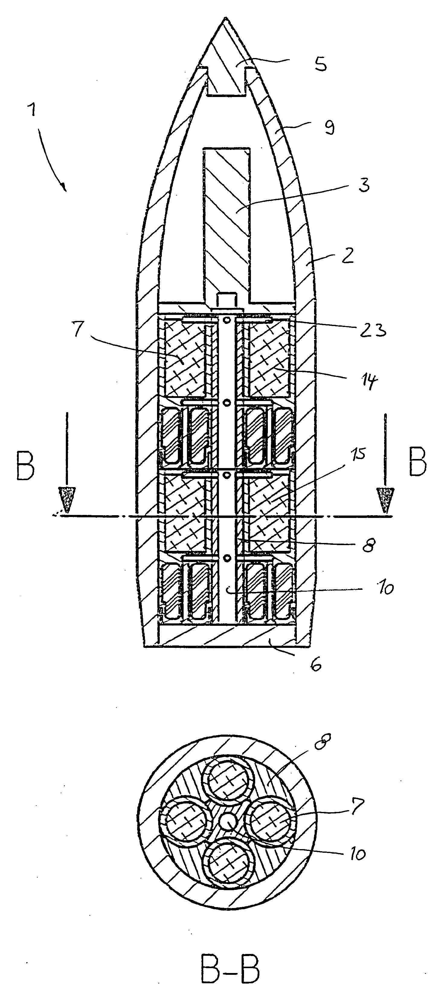
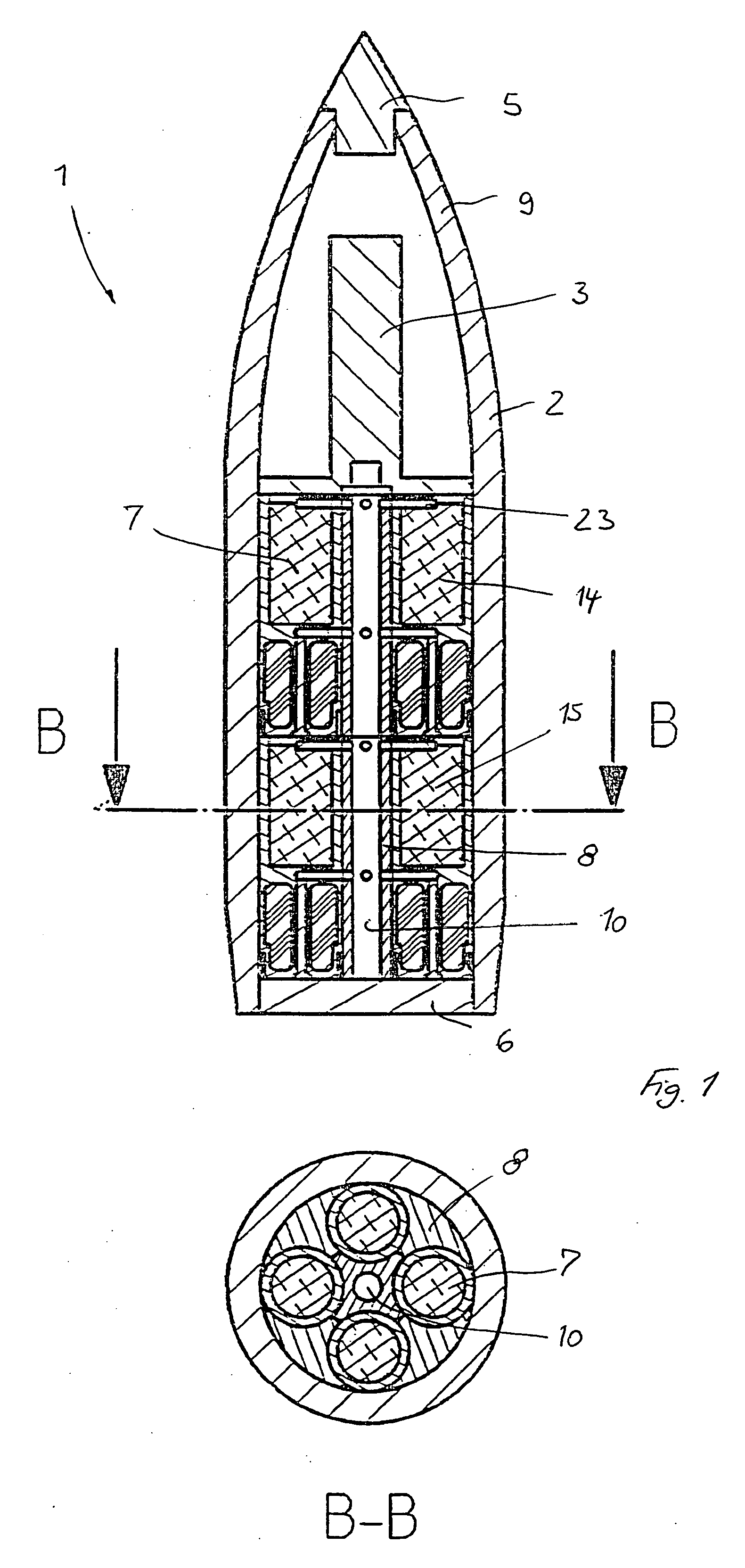
[0023]FIG. 1 shows a projectile 1, which consists of a projectile body 2, an expulsion charge 3 and an expulsion plate. Besides a projectile fuse 5 and a projectile base 6, the projectile 1 contains flare bodies 7 and filler elements 8. In the present case, the flare bodies 7 are positioned on two levels 14, 15. In the case illustrated here, eight flare bodies 7 are incorporated in the projectile 1. The filler elements 8 preferably form a central channel 10 in the projectile 1 for the expulsion gases, by which the delay elements 11, 12 of the flare bodies 7 are ignited.

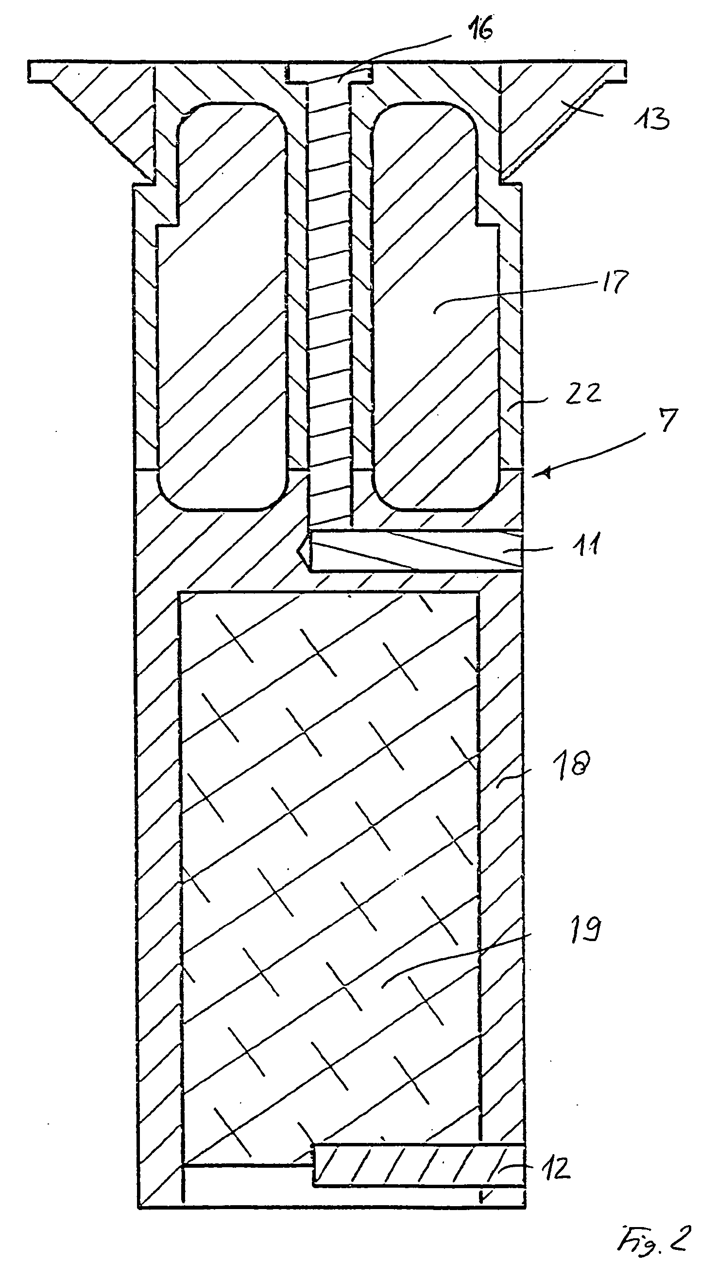
[0024]The individual flare body 7 itself consists of a jacket 18, which houses, for example, a pyrotechnic compound 19, then, at least in this case, preferably two delay elements 11, 12 or a twin-stage delay element, an expulsion system 16, 22, and a parachute 17 (FIG. 2). A stabilizing element 13 is located on the outer jacket, but this is not absolutely necessary.

[0025]The time after which the expulsion charge 3 is ...


PUM


Abstract

A projectile with several flare bodies, which are eccentrically housed in the body of the projectile and are ignited by at least one delay element for each flare body. The expulsion gases are conveyed from the ogive of the projectile to the delay elements through filler elements that form a channel in the center of the projectile for the expulsion gases.

Description

BACKGROUND OF THE INVENTION[0001]The invention concerns a munition, a projectile, or the like with several flare bodies for battlefield illumination.[0002]Flare munition for battlefield illumination is either shot from a weapon, e.g., a mortar, (illuminating grenade) or dropped from a missile such as a bomb (illuminating bomb). It consists basically of a slowly burning pyrotechnic material (for example, a magnesium compound), which is expelled from the munition a predetermined time after the munition has been fired, and floats to the ground on a parachute. During its descent, the flare body emits light in the visible and / or infrared wavelength range, thereby illuminating a target or target area.[0003]As is well known, flare projectiles contain a single flare body. The flare body is expelled from the body of the projectile by an expulsion charge after a period of time that can be set in the time fuse. Alternatively, in artillery shells, the base separates during the expulsion, and th...

Claims


Application Information

Patent Timeline
IPC IPC(8): F42B4/26
CPCF42B12/62F42B12/42F42B4/28F42B4/26
Inventor DAU, OLESACKARNDT, ALFONSNADERHOFF, UWESCHWENZER, MICHAELAUMUND-KOPP, RALFTHAPE, MANFREDMUNZNER, SEBASTIANRYBOL, MARTIN
Owner RHEINMETALL WAFFE MUNITION GMBH
Features
  • R&D
  • Intellectual Property
  • Life Sciences
  • Materials
  • Tech Scout
  • Unparalleled Data Quality
  • Higher Quality Content
  • 60% Fewer Hallucinations
Learn More