Combination Planer/Moulder With Adjustable Vertical Support and Method of Adjustment

Active Publication Date: 2009-06-18
WOODSTOCK INT
View PDF5 Cites 3 Cited by
  • Summary
  • Abstract
  • Description
  • Claims
  • Application Information

AI Technical Summary

Benefits of technology

[0007]In accordance with the present invention a wood working device is provided. The device, a planer / moulder for such uses as creating moldings used in construction, includes a table for the placement of the material to be shaped and an adjustment system for adjusting the cutterhead of the device relative to the table, and materials, to be worked. Materials, such as wood, are placed on a table or platform and the cutterhead, having knives therein, is adjusted to a desired position proximate to the materials. Locking means are provided to secure the cutterhead at the desired position so that work on the materials can be completed accurately. In preferred embodiments of the present invention, the adjustment system includes at least one column, having a dovetail-shaped cross-section acting as a rail, or way, with rectilinear walls onto which the cutterhead can be raised and lowered. By using a rail having a dovetail shaped cross-section with a rectilinear wall, when the cutterhead is placed at an elevation and pressure is placed against the wall effectively locking the cutterhead height to the column, the cutterhead remains in a material shaping position until moved, or unlocked manually.
[0009]Further, in some embodiments, the locking means of the present invention includes an enlarged opening in the casting table for the fitment of a gib. A gib is placed within the opening such that the locking means can press the gib against the rectilinear wall of the column; in this way the gib adds surfaces to accept the wear associated with such locking means. The gib, as it wears, can be easily replaced to keep the locking means of the device working well such that the placement of the cutterhead is maintained through compression of the gib by the locking means against the dovetail-shaped columns until released.
[0011]It will be understood that the device of the present invention provides a method of accurately planing or moulding materials. The method includes the steps of providing a table, a stand and a cutterhead, the cutterhead configured to either plane or mould materials and providing an adjustment system having at least one column attached to the stand, the at least one column having at least one rectilinear wall that acts as a rail onto which the cutterhead can be raised and lowered relative to the table. As described above, a locking means is also provided and by engaging the locking means the cutterhead is pressed against the column fixing the cutterhead at a desired elevation on the column. The desired location, as understood by persons having skill in the art, is to place the cutterhead in planing or moulding contact with the material to be planed or moulded such that engaging the cutterhead causes accurate planing or moulding of the material. As noted above, in a preferred embodiment of the method of using the device, a gib is placed in the device in association with the cutterhead such that when the locking means is engaged the gib is pressed against a rectilinear wall of the column, thereby holding the device in place for planing and moulding. The locking means includes a rod and threaded knob, the rod and knob being joined together, the knob being in threaded engagement with the cutterhead and the rod being in contact with the gib, at the distal end of the rod, such that when the knob is threaded into the cutterhead, the rod presses the gib against the column. Advantageously, the device of the present invention further includes a transparent window, preferably made of plastic materials such as Plexiglas®, such that the user may place the cutterhead in the desired position, to provide the desired shaping, while being able to view the materials and / or the cutterhead. It has been determined that hand-eye coordination in, moulding operations provides the best results. Further, the window permits the user to view and then clear any chaff from the cutterhead prior to working.

Problems solved by technology

The use of rounded surfaces such as the columns, rods, screws and stops used in the above noted prior art generally provide inadequate holding power for a cutterhead system.
Further, with time and usage, such systems are known to wear, causing slippage of the cutterhead relative to the table surfaces.
It is known that the mating surfaces of the round columns and cooperative support casting or table eventually wear away due to the friction caused by continually adjusting and readjusting their relative positions as required by the machine's use.
This causes looseness or “play” to develop in the system for which, as a result of the configurations, there is no ultimate adjustment; the machines must be overhauled with replacement of many parts.
Further, it is costly to remedy this as replacement of the round columns and upper support casting is usually eventually necessary.
Such a procedure requires replacement parts and technician time and is costly and time consuming, keeping a working machine away from work.
Generally in the past, woodworking, including planning, molding and shaping for which such devices have been used has not been exacting as the locking mechanisms used with the round column system of support are by their nature only able to apply pressure in a very small area on the columns.
Consequently, the actual clamping force available to secure the cutterhead assembly is small and often inadequate to the task; allowing slippage of the cutterhead assembly and consequently continual re-tightening.
Such continual adjustments take away from actual work time as well.
As machines wear this effect becomes progressively worse and rather than replace parts or get new machines, lesser quality work has become acceptable up to the point of the potential failure of the machines of the past.
However, such mechanisms have not been used in woodworking machines because of the significant differences in these devices, including the added weight in a metal working machine, the costs of redesigning accepted machinery and the generally diametric differences in the developments and evolution of wood and metal working machines.
Further, wood working machines of the past have also suffered in that once the cutterhead is put into position and locked into place and the subject wood is fed into the device, the user can not see the results of the work until the material emerges from the machine.
If the machine is incorrectly set, or if the adjustments of the height and position have been compromised as a result of slippage, as described above, or if material chips or waste products are interdicting the cutting knives, or for other reasons, a poorly shaped piece of moulding would emerge and would comprise a lost or wasted piece of material.
With the increased costs of materials such waste is unconscionable and can be the difference in a profit or loss in a project.
Further, the wasting of natural resources has become disfavored, especially as conservation is now sought in projects and is popular.

Method used


Image

  • Combination Planer/Moulder With Adjustable Vertical Support and Method of Adjustment
  • Combination Planer/Moulder With Adjustable Vertical Support and Method of Adjustment
  • Combination Planer/Moulder With Adjustable Vertical Support and Method of Adjustment

Examples


Embodiment Construction

[0029]While the present invention is susceptible of embodiment in various forms, there is shown in the drawings a number of presently preferred embodiments that are discussed in greater detail hereafter. It should be understood that the present disclosure is to be considered as an exemplification of the present invention, and is not intended to limit the invention to the specific embodiments illustrated. It should be further understood that the title of this section of this application (“Detailed Description of an Illustrative Embodiment”) relates to a requirement of the United States Patent Office, and should not be found to limit the subject matter disclosed herein.

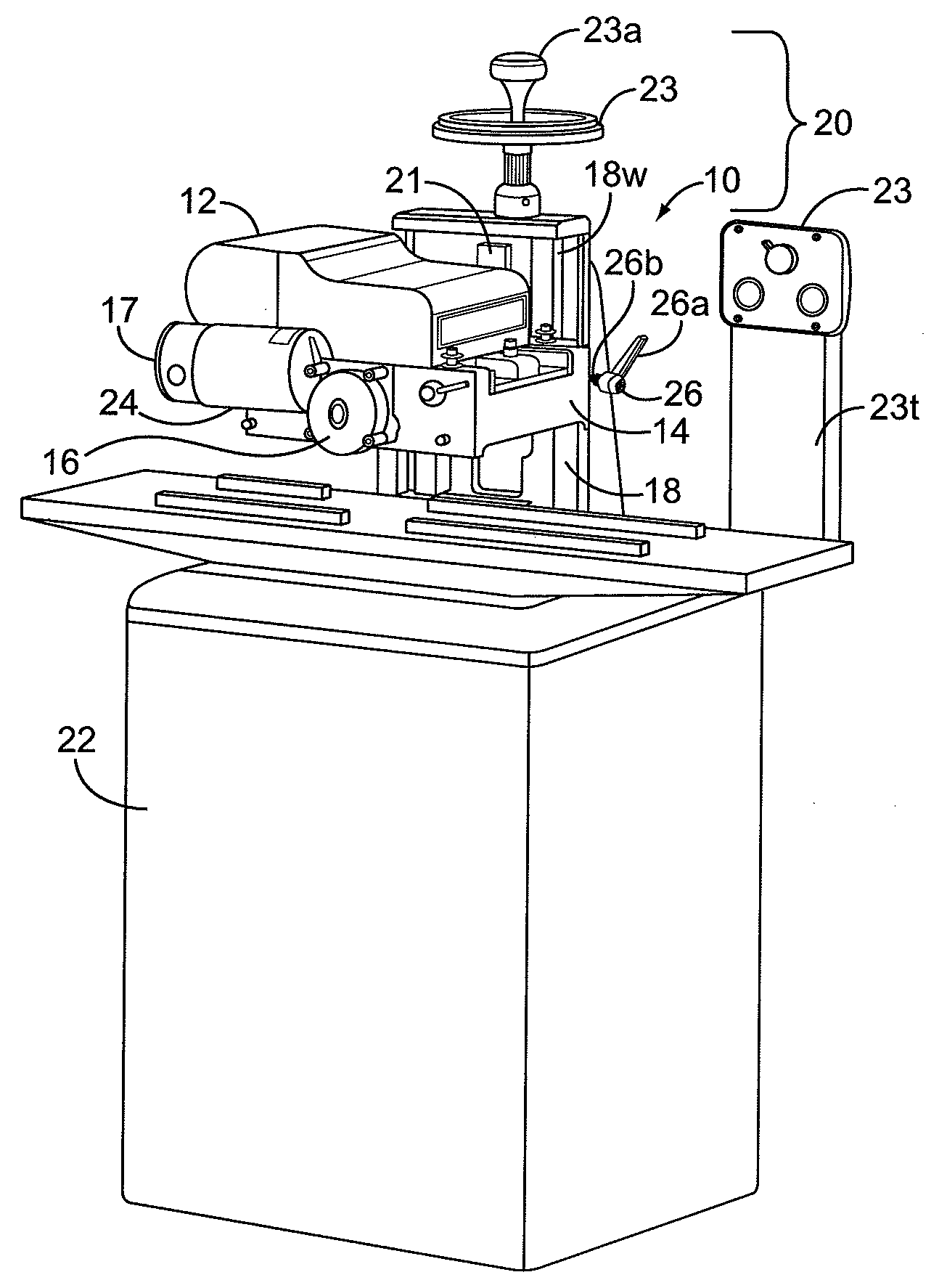
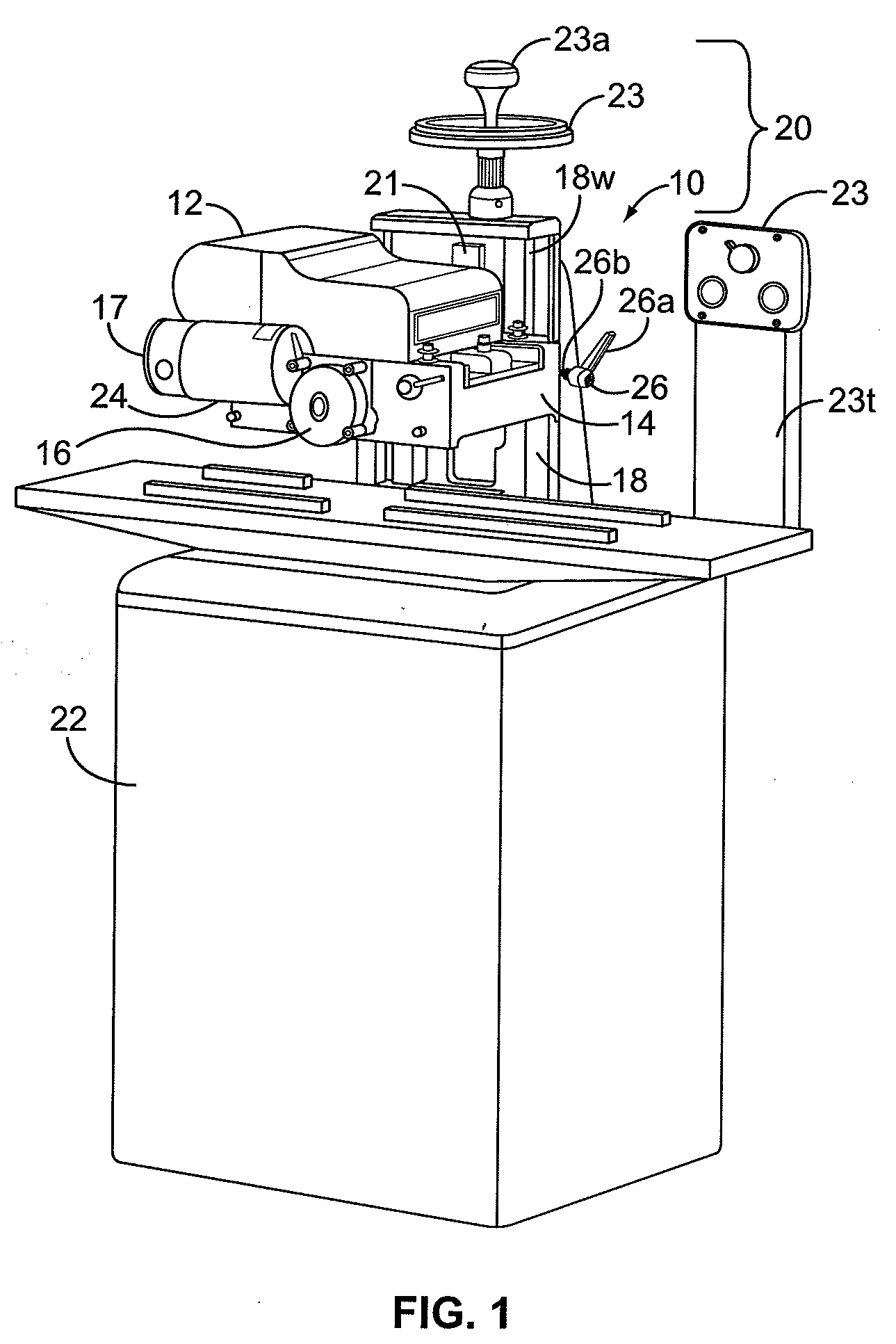
[0030]Referring now to the drawings, FIG. 1 shows a planer / moulder device of the present invention. FIG. 1 shows a planer / moulder device 10, the upper assembly 12, the cutterhead casting 14, cutterhead 16, dovetail wall 18, dovetail ways 18w, support structure 20, the device cabinet 22 and a viewing window 24. It will b...


PUM

PropertyMeasurementUnit
Transparencyaaaaaaaaaa

Abstract

A combination planer / moulder having means to raise, lower and lock a cutting member at a desired position is provided. The device includes a platform onto which a table for holding materials and an adjustment system are attached. The adjustment system includes at least one column having a rectilinear wall. A cutterhead is provided, having cooperative openings and a locking means, such that it may move along the at least one column of the adjustment system and locked in place. The rectilinear wall of the column cooperates with a similarly shaped opening in the cutterhead, such that by pressing the rectilinear shaped side of the opening against the rectilinear wall of the column the cutterhead may be fixed in desirable positions to permit work on materials and released for adjustment. The device includes a window such that the placement of the cutting knives on the materials can be viewed and debris can be seen and removed therefrom.

Description

FIELD OF THE INVENTION[0001]The present invention concerns a combination machine for woodworking. A combination machine is one that associates the functions of two or more separate machines into a single unit; combining such functions as carving and smoothing or others. More particularly the present invention concerns a combined planer and moulder having an improved system of moving and affixing the cutterhead of the device relative to the material to be worked to aid in preparing wood worked pieces.BACKGROUND OF THE INVENTION[0002]Existing planers and moulders on the market use round columns to support and guide the cutterhead of the device as it is moved up or down relative to the position of the material to be planed and / or moulded. Typically four columns are used such that the columns are placed on each of the four corners of the cutting plane of the device. Some planer moulders of the prior art include: Grizzly Industrial, Inc. of Bellingham Wash. models G1017 12″ Planer, G1021...

Claims


Application Information

Patent Timeline
IPC IPC(8): B27C9/00B27C1/00
CPCB27C1/04Y10T409/307952Y10T409/308176B27C1/14
Inventor BALOLIA, SHIRAZ
Owner WOODSTOCK INT
Why Eureka
Try Eureka