Automotive alternator including annular core having protrusions and recesses alternately formed on its outer surface

a technology of alternators and annular cores, which is applied in the direction of rotating magnets, synchronous machines with stationary armatures, magnetic circuit rotating parts, etc., can solve the problems of large windage loss, large magnetoresistance between, and affect the quietness of the alternator, so as to reduce the leakage of magnetic flux

Inactive Publication Date: 2009-06-18
DENSO CORP
View PDF5 Cites 18 Cited by
  • Summary
  • Abstract
  • Description
  • Claims
  • Application Information

AI Technical Summary

Benefits of technology

[0014]In yet another preferred embodiment of the invention, the rotor further includes a plurality of permanent magnets, each of which is interposed between a circumferentially adjacent pair of the magnetic pole claws of the first and second magnetic pole cores so as to reduce magnetic flux leakage between the pair of the magnetic pole claws.

Problems solved by technology

Further, the magnetic pole claws, which are located on the radially outer side of a field winding, will generate loud wind noises during high-speed rotation thereof, impairing the quietness of the alternator and causing a large windage loss.
However, such an air gap will cause a large magnetoresistance between the magnetic pole cores and the stator core.

Method used


Image

  • Automotive alternator including annular core having protrusions and recesses alternately formed on its outer surface
  • Automotive alternator including annular core having protrusions and recesses alternately formed on its outer surface
  • Automotive alternator including annular core having protrusions and recesses alternately formed on its outer surface

Examples


first embodiment

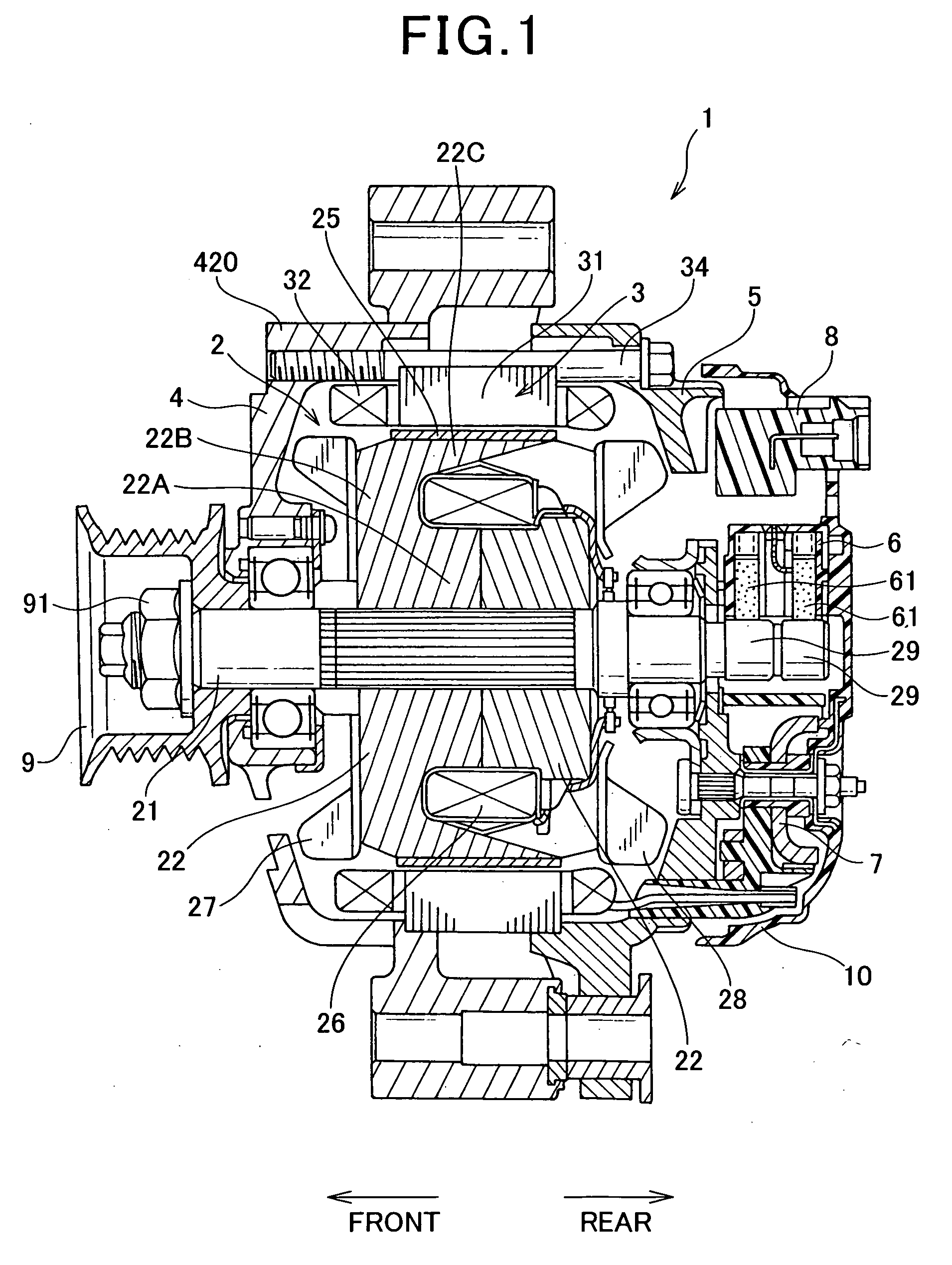
[0028]FIG. 1 shows the overall configuration of an automotive alternator 1 according to the first embodiment of the invention. The alternator 1 is designed for use in a motor vehicle, such as a passenger car or a truck.

[0029]As shown in FIG. 1, the alternator 1 includes a rotor 2, a stator 3, a front housing 4, a rear housing 5, a brush assembly 6, a rectifier 7, a voltage regulator 8, a pulley 9, and a rear cover 10.

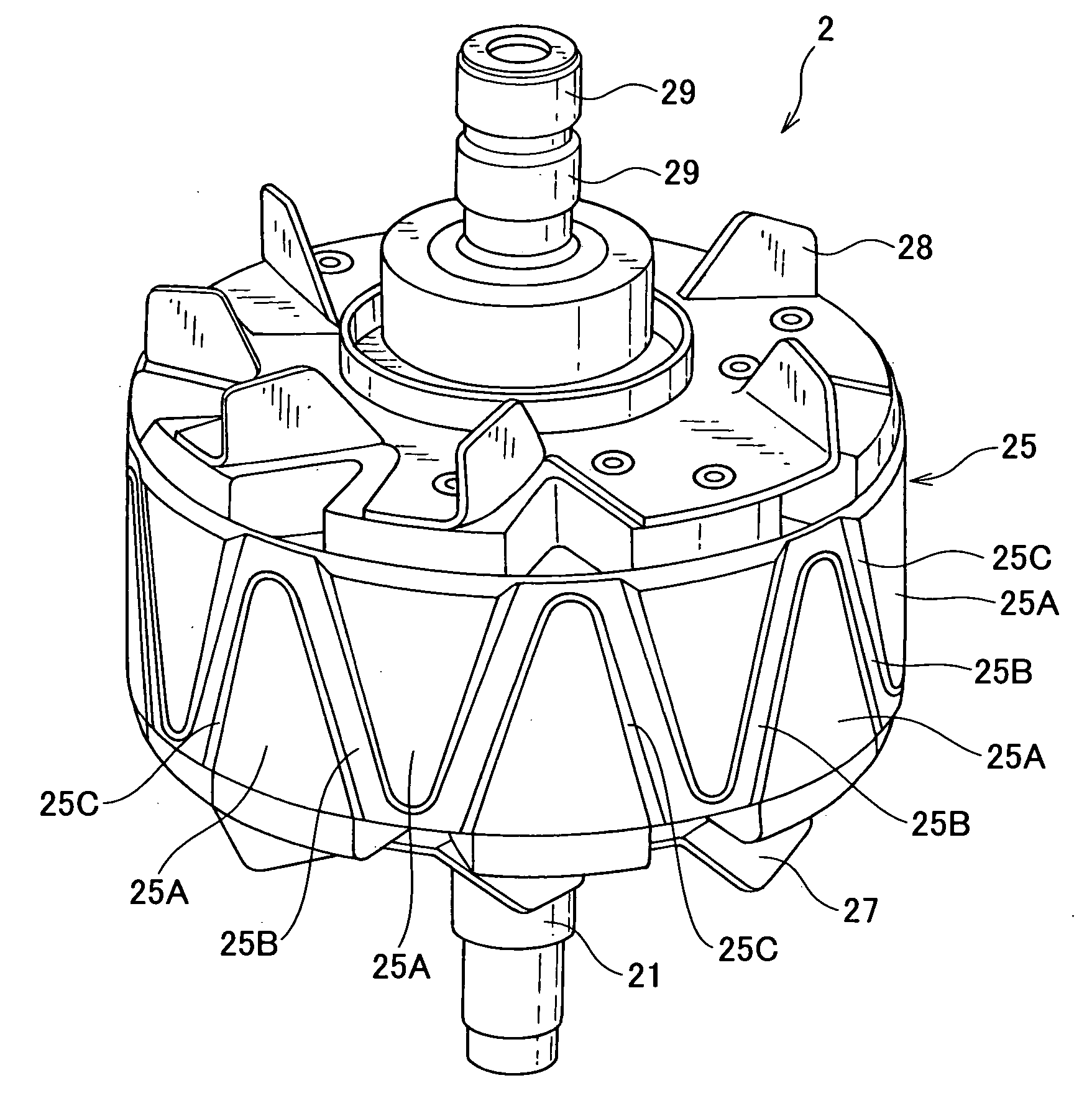
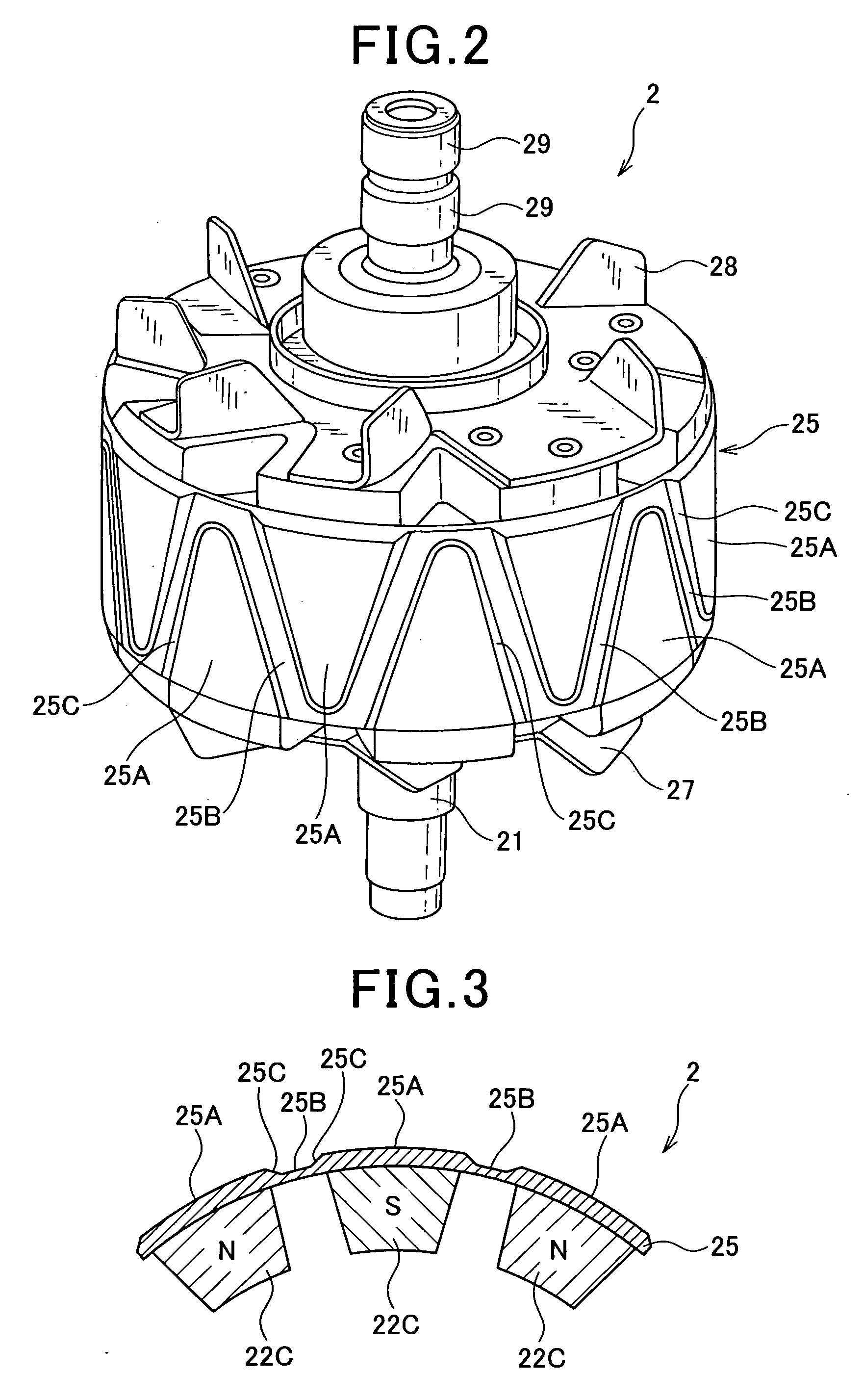
[0030]The rotor 2 includes a rotary shaft 21, a pair of first and second lundell-type magnetic pole cores 22, an annular core 25, a field winding 26, and cooling fans 27 and 28.

[0031]The rotary shaft 21 is rotatably supported by the front and rear housings 4 and 5. On a rear end portion of the rotary shaft 21, there is provided a pair of slip rings 29 that are electrically connected to opposite ends of the field winding 26, respectively.

[0032]Each of the first and second magnetic pole cores 22 has a hollow cylindrical boss portion 22A, a disc portion 22B, and a pluralit...

second embodiment

[0065]FIG. 4 shows a rotor 2A according to the second embodiment of the invention.

[0066]As shown in FIG. 4, the rotor 2A includes, instead of the annular core 25 of the first embodiment, an annular core 125.

[0067]The annular core 125 is made of a laminate that is formed by laminating a plurality of soft magnetic lamination sheets in the axial direction of the annular core 125 (i.e., in the axial direction of the rotary shaft 21).

[0068]With the above formation of the annular core 125, it is possible to reduce eddy current induced in the annular core 125, thereby improving the efficiency of the alternator 1.

third embodiment

[0069]FIG. 5 shows part of an annular core 225 according to the third embodiment of the invention.

[0070]As shown in FIG. 5, the annular core 225 has, for each of the recesses 25B, two through-holes 25D that penetrate a wall portion of the annular core 225, which defines the bottom of the recess 25B, in the axial direction of the annular core 225 (i.e., in the axial direction of the rotary shaft 21).

[0071]With the through-holes 25D, it is possible to further effectively reduce the leakage magnetic flux flowing inside the annular core 225 in the circumferential direction of the rotary shaft 21, thereby further increasing the output power of the alternator 1.

[0072]In addition, it should be noted that the annular core 225 may have a different number of the through-holes 25D for each of the recesses 25B, for example one or three.


PUM


Abstract

An automotive alternator is disclosed which includes an annular core disposed to surround the radially outer peripheries of all magnetic pole claws of magnetic pole cores. The annular core has, on an outer surface thereof, a plurality of protrusions, a plurality of recesses, and a plurality of slopes. Each of the protrusions is so provided as to be coincident with a corresponding one of the magnetic pole claws of the magnetic pole cores in the circumferential direction of a rotary shaft. Each of the recesses is alternately formed with the protrusions so as to be coincident with a corresponding one of air gaps formed between the magnetic pole claws of the magnetic pole cores in the circumferential direction. Each of the slopes is inclined to the radial direction of the rotary shaft and connects a circumferentially adjacent pair of one of the protrusions and one of the recesses.

Description

CROSS-REFERENCE TO RELATED APPLICATION[0001]This application is based on and claims priority from Japanese Patent Application No. 2007-321942, filed on Dec. 13, 2007, the content of which is hereby incorporated by reference in its entirety into this application.BACKGROUND OF THE INVENTION[0002]1. Technical Field of the Invention[0003]The present invention relates generally to automotive alternators for use in motor vehicles, such as passenger cars and trucks. More particularly, the invention relates to an automotive alternator which includes an annular core having protrusions and recesses alternately formed on its outer surface.[0004]2. Description of the Related Art[0005]In recent years, engine compartments in motor vehicles have been reduced to meet the requirements of adopting a slant-nose design to reduce the vehicle running resistance and securing a more sufficient space in the passenger compartment; thus, the spaces available for installation of automotive alternators in engin...

Claims


Application Information

Patent Timeline
Patent Type & Authority Applications(United States)
IPC IPC(8): H02K1/22
CPCH02K21/044
Inventor ISOGAI, NOBUO
Owner DENSO CORP
Why Eureka
Try Eureka