Optical scanning apparatus and color image forming apparatus
- Summary
- Abstract
- Description
- Claims
- Application Information
AI Technical Summary
Benefits of technology
Problems solved by technology
Method used
Image

Examples
first embodiment
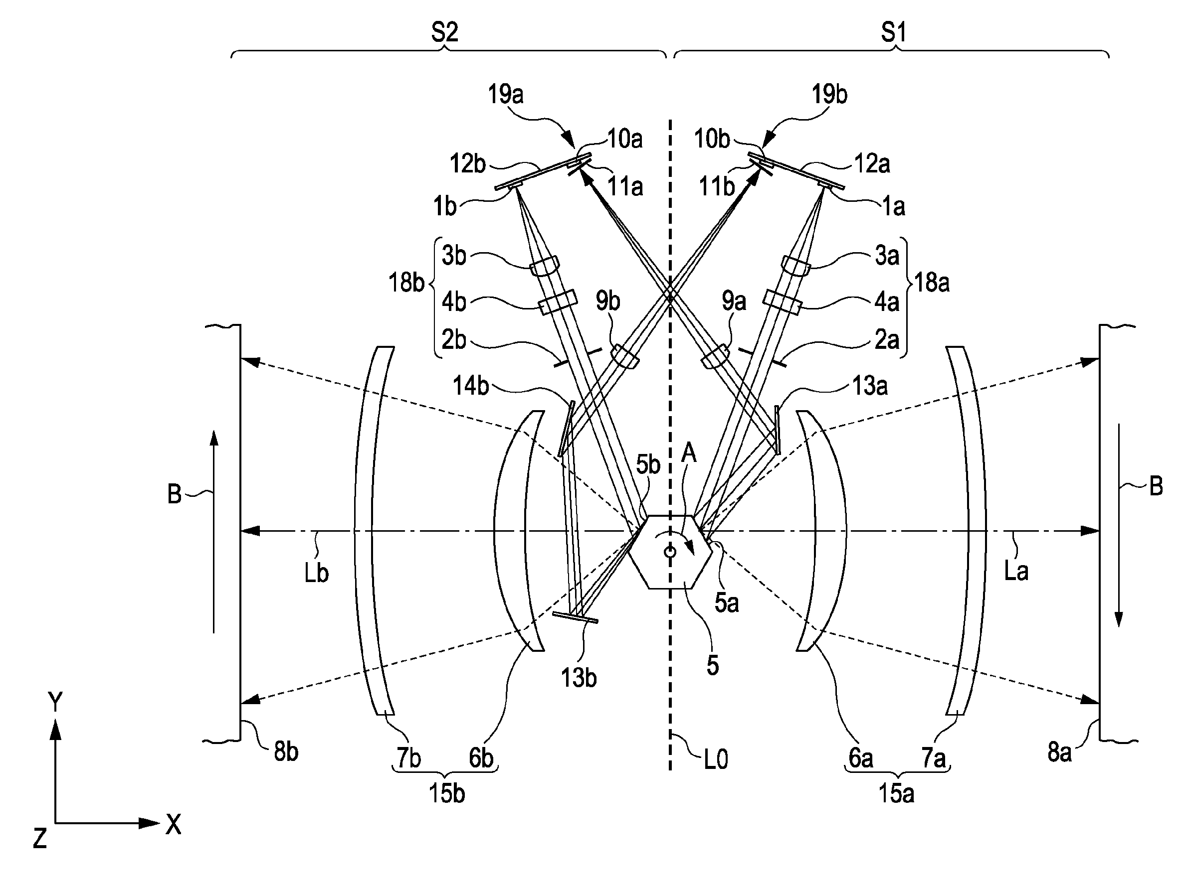
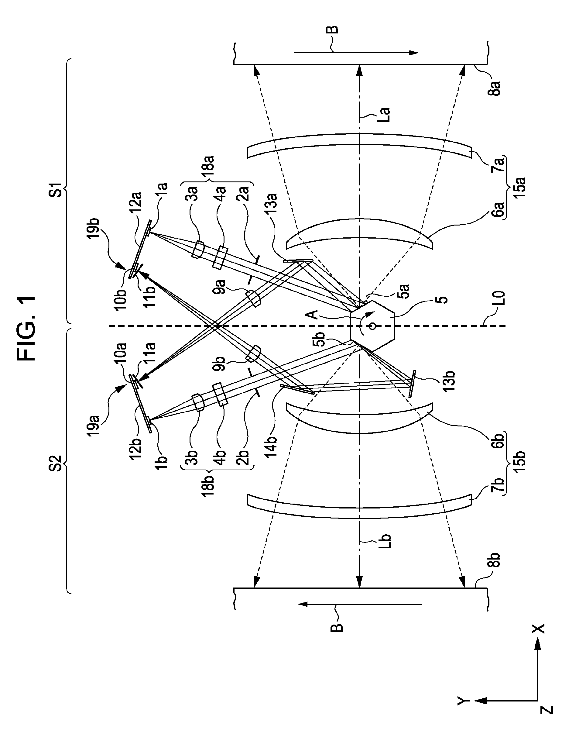
[0052]FIG. 1 is a sectional view of an important part of an optical scanning apparatus according to a first embodiment of the present invention, taken along the main scanning direction (main scanning sectional view). FIG. 2 is a sectional view of an important part of the optical scanning apparatus according to the first embodiment, taken along the subscanning direction (subscanning sectional view).
[0053]Herein, the “main scanning direction (Y direction)” is the direction in which the light beams deflected by the deflecting surfaces of the deflecting unit are scanned. The “subscanning direction (Z direction)” is the direction parallel to the axis of rotation of the deflecting unit. The “main scanning cross-section” is a plane normal to the subscanning direction (Z direction). The “subscanning cross-section” is a plane normal to the main scanning direction (Y direction).
[0054]In the drawings, S1 and S2 denote first and second scanning units (hereinafter also referred to as “stations”)...
second embodiment
[0117]FIG. 6 is a main scanning sectional view of an important part of an optical scanning apparatus according to a second embodiment of the present invention. In FIG. 6, like reference numerals refer to like parts shown in FIG. 1.
[0118]Because structures and optical functions of the first and second scanning units S1 and S2 according to the present embodiment are substantially the same, the following description will be given on the basis of the first scanning unit S1. The reference numerals in parenthesis denote components of the second scanning unit S2 corresponding to those of the first scanning unit S1.
[0119]The optical scanning apparatus according to the present embodiment is different from that according to the first embodiment in that the synchronous detection mirror 13a (13b, 14b) is arranged between the first imaging lens 6a (6b) and the scan surface 8a (8b). Because the other structures and optical functions of the optical scanning apparatus according to the present embod...
third embodiment
[0151]FIG. 8 is a main scanning sectional view of an important part of an optical scanning apparatus according to a third embodiment of the present invention. In FIG. 8, like reference numerals refer to like parts shown in FIG. 1.
[0152]The optical scanning apparatus according to the present embodiment is different from that according to the first embodiment in that the synchronous detection optical system is provided in only one of the first and second scanning units S1 and S2. Because the other structures and optical functions of the optical scanning apparatus according to the present embodiment are the same as those according to the first embodiment, the optical scanning apparatus according to the present embodiment has the same effect as that according to the first embodiment.
[0153]According to the present embodiment, only the first scanning unit S1 has the synchronous detection optical system 19a.
[0154]Parameters associated with the arrangement and optical characteristics of th...
PUM
 Abstract
Description
Claims
Application Information
 - Generate Ideas
- Intellectual Property
- Life Sciences
- Materials
- Tech Scout
- Unparalleled Data Quality
- Higher Quality Content
- 60% Fewer Hallucinations
Browse by: Latest US Patents, China's latest patents, Technical Efficacy Thesaurus, Application Domain, Technology Topic, Popular Technical Reports.
© 2025 PatSnap. All rights reserved.Legal|Privacy policy|Modern Slavery Act Transparency Statement|Sitemap|About US| Contact US: help@patsnap.com