Vertically Aligned Liquid Crystal Display

Inactive Publication Date: 2009-06-18
SANYO ELECTRIC CO LTD
View PDF9 Cites 0 Cited by
  • Summary
  • Abstract
  • Description
  • Claims
  • Application Information

AI Technical Summary

Benefits of technology

[0019]With the above structure, the present invention reduces the influence at edge sections of the pixel electrodes by the combination of the above mentioned orientation controller and the pixel electrodes, thereby achieving improved viewing angle characteristic and transmittance and a reduced average response time of the display.
[0020]As is apparent from the above description, the influence at the edge sections of the pixel electrode is reduced, the viewing angle characteristic and the transmittance are improved, and the average response time is shortened by setting an aspect ratio (V / H) of each pixel electrode or each divided pixel electrode to at least a predetermined value.

Problems solved by technology

Thus, as the viewing angle changes, the light intensity or the color phase of the transmitted light also changes, causing a so-called viewing angle dependency problem.
Problems of decreased transmittance and slower response speed also remain.

Method used


Image

  • Vertically Aligned Liquid Crystal Display
  • Vertically Aligned Liquid Crystal Display
  • Vertically Aligned Liquid Crystal Display

Examples


second embodiment

[0034]Referring next to FIGS. 6 and 7, the present invention will be described.

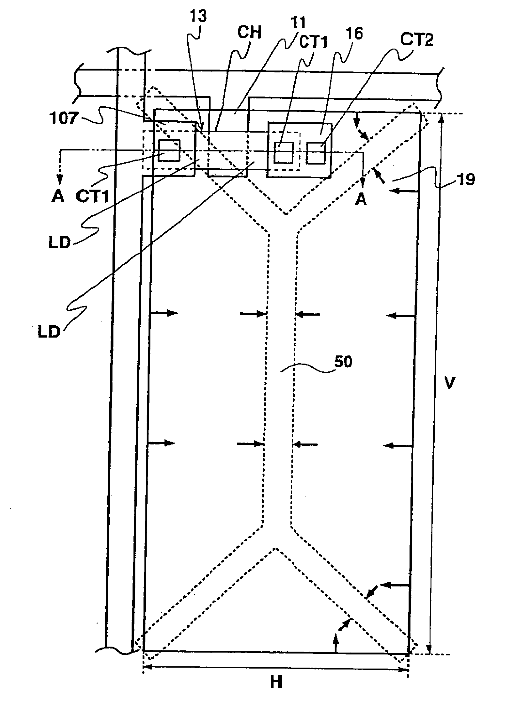
[0035]FIG. 6 is a plan view showing a unit pixel structure of a liquid crystal display and FIG. 7 is a sectional view taken along line A-A of FIG. 6. It is to be noted, that for the sake of clarity the TFT structure is not shown in FIG. 7, but it is of the same structure as that shown in FIG. 4.

[0036]In this embodiment, the vertical length of the pixel electrode 19 corresponding to the unit pixel is longer than the horizontal length. In this structure, slits 19d and 19e are formed in the vertical direction in the pixel electrode 19 like a comb, to divide (in this embodiment, the pixel electrode is divided equally) the pixel electrode 19 into three pixel electrode regions 19a, 19b, and 19c such that the aspect ratio V / H of each pixel electrode region is 2 or greater. It is to be noted, however, these pixel electrode regions 19a, 19b, and 19c are partly connected to each other under the slits 19d and 19e, b...

first embodiment

[0037]In this case, orientation control windows 32a, 32b, and 32c are formed in the common electrode 31 formed on the opposing substrate 30, each window corresponding to each pixel electrode region 19a, 19b, and 19c. In each pixel electrode region 19a, 19b, and 19c, the liquid crystal molecules are oriented in the reverse directions about each orientation control window. This increases the area where the orientation is uniform while decreasing the area of an abnormal orientation at the edge sections of the pixel electrode. Thus, the viewing angle characteristic, transmittance, and response time can be improved, similar to the above

[0038]FIG. 8 is a sectional view showing another structure of an orientation controller. FIG. 8 is similar to FIG. 7 in that both FIGS. 7 and 8 are sectional views along the A-A line of FIG. 6. In FIG. 7, orientation control windows 32a, 32b, and 32c are formed in the common electrode 31 as the orientation controller (orientation divider) for controlling t...


PUM


Abstract

A vertically aligned type liquid crystal display includes a liquid crystal layer disposed between pixel electrodes and a common electrode and containing vertically aligned liquid crystal molecules, the orientation of the liquid crystal molecules being controlled by an electric field. An orientation controller is formed on the common electrode at a position opposing the pixel electrode and an aspect ratio, i.e., a vertical to horizontal length ratio of the pixel electrode is set to at least 2. Alternatively, the pixel electrode is partitioned into at least two electrode regions so that each region represents a divided pixel electrode.An orientation controller is formed on the common-electrode so as to correspond to each divided pixel electrode, an aspect ratio of each divided pixel electrode is set to at least 2. As such, the influence at the edge sections of the pixel electrode is reduced, viewing angle characteristic and transmittance are improved, and average response time is shortened.

Description

[0001]This application is a continuation in part of U.S. patent application Ser. No. 09 / 768,371 filed on Jan. 23, 2001, which in turn is a divisional application of a Continued prosecution application filed on Jun. 18, 1999 of U.S. patent application Ser. No. 09 / 162,984 filed on Sep. 29, 1998.BACKGROUND OF THE INVENTION[0002]1. Field of the Invention[0003]The present invention relates to a liquid crystal display (LCD) which utilizes opto-electric anisotropy of liquid crystal, and more particularly to a liquid crystal display which achieves an improved response speed and transmittance.[0004]2. Description of the Related Art[0005]LCDs are compact, thin, and low power consumption devices and have been developed for practical use in the field of office automation (OA) and audio-visual (AV) equipment. In particular, active matrix type LCDS which utilize thin film transistors (TFTs) as switching elements are theoretically capable of static actuation at a duty ratio of 100% in a multiplexi...

Claims


Application Information

Patent Timeline
IPC IPC(8): G02F1/1343G02F1/1337G02F1/1333G02F1/136G02F1/1368G02F1/139
CPCG02F1/133707G02F1/1343G02F2001/134318G02F2201/121G02F1/1393G02F1/1337G02F1/136G02F1/134318
Inventor KOMA, NORIO
Owner SANYO ELECTRIC CO LTD
Why Eureka
Try Eureka