Image forming device and image forming method
a technology of image forming and forming device, which is applied in the direction of digitally marking record carriers, instruments, electrographic processes, etc., can solve the problems of increasing the size of the machine and the cost of the equipmen
Inactive Publication Date: 2009-06-18
FUJIFILM BUSINESS INNOVATION CORP
View PDF14 Cites 16 Cited by
- Summary
- Abstract
- Description
- Claims
- Application Information
AI Technical Summary
Benefits of technology
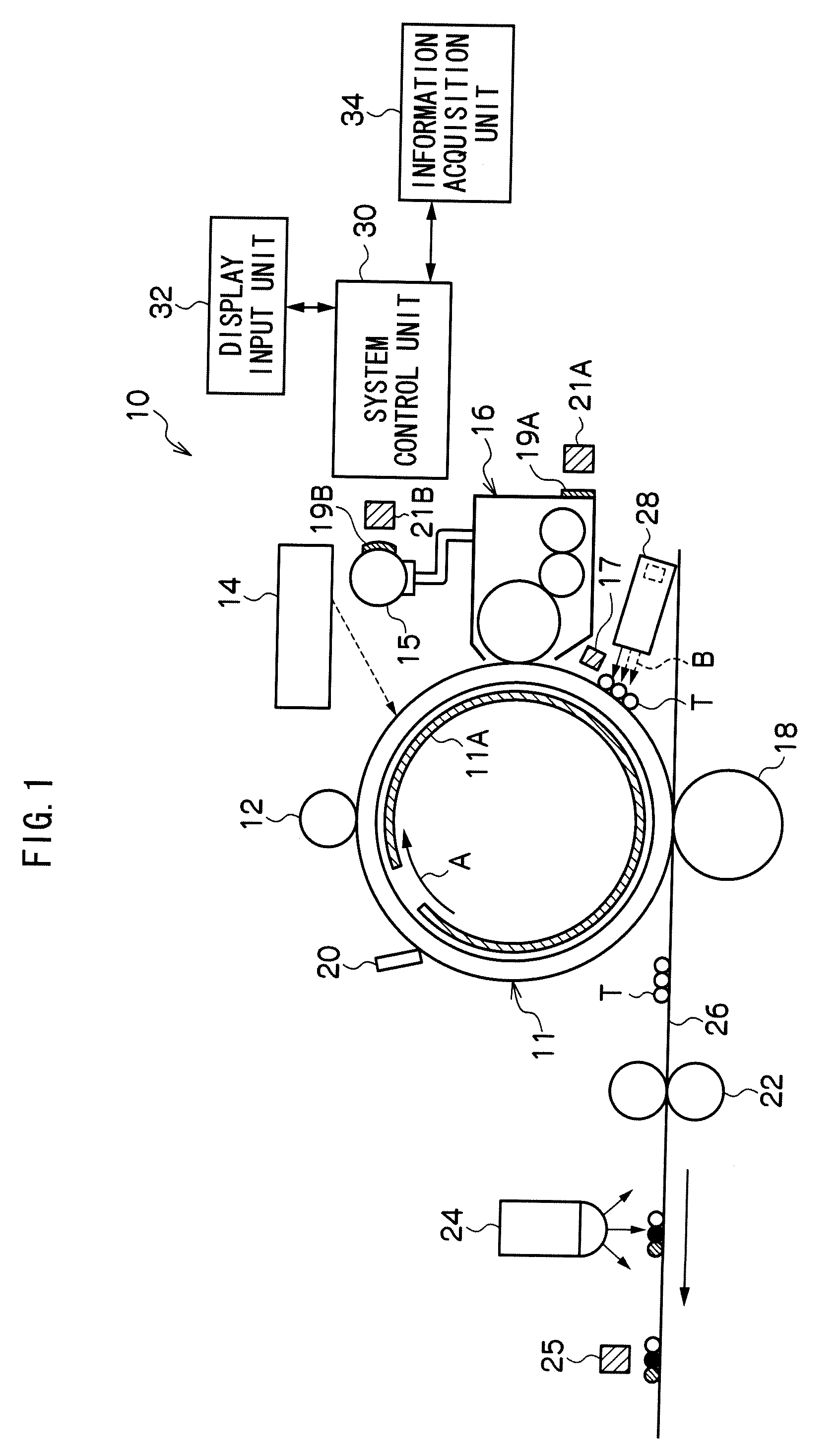
[0051]By the exposure device 14, the photoreceptor 11 charged with the charging device 12 is exposed to a light to form an electrostatic latent image. Any one of known exposure devices may be used as the exposure device 14 for forming an electrostatic latent image. Examples of the exposure device 14 include a laser scanning system using a ROS (raster output scanner), a LED image bar system, an analog light-exposure unit, an ion-current control head, and the like. As shown by arrow A in FIG. 1, the surface of the photoreceptor 11 can be subjected to exposure by irradiating it with a beam from a light source (not shown) of the exposure device 14. In addition, a new light-exposure unit to be developed in the future may also be used as long as the advantageous effects of aspects of the invention are obtained.
[0052]The wavelength of the light irradiated from the exposure device 14 to the photoreceptor 11 is in the spectral sensitivity region of the photoreceptor 11. The photosensitive layer of the photoreceptor 11 is a layer hardly showing absorption in the wavelength range of exposure lights to provide color-generation information. Accordingly, lights in a wavelength range adjusted to the absorption wavelength range of the photoreceptor 11 are used. For example, when the absorption wavelength range of the photoreceptor 11 is 700 nm or more, a semiconductor laser having a wavelength at 780 nm as exposure light is preferably used.
[0053]Irradiation on the photoreceptor 11 is performed at the toner-developing position described below in the case of reversed development and to the position other than the toner-developing position in the case of normal development, for example, at a light amount of the logical sum of pieces of image-forming information for the 4 colors. The irradiation-spot diameter is preferably in the range of 40 to 80 μm in order to control the resolution at 600 to 1,200 dpi.
[0054]As for the exposure energy, the electric potential in the exposed region on the photoreceptor 11 (post-exposure electric potential) is preferably in the range of about 5 to 30% of the charging potential described above. The amount of the toner developed onto the photoreceptor 11 can be regulated by regulating the amount of exposure light, and the amount of an adhering toner image can be regulated. By altering the amount of exposure light according to the adhesion amount necessary for each exposure position, the amount of the toner to be developed can be varied.
[0055]On the other hand, in the case of the ionography, a latent image is formed on the photoreceptor with an ionic writing head (ionic writing step). Examples of the ionic writing heads include those controlling on / off of the ion current according to image signal (Japanese Patent Application Laid-Open (JP-A) No. 4-122654), those controlling on / off of the ion current generation (JP-A No. 6-99610), and the like, A dielectric material as well as a photoreceptor may be used as the photoreceptor in such a system.
[0057]The developing device 16 forms a developed toner image corresponding to the electrostatic latent image on the photoreceptor 11 by developing the electrostatic latent image with a toner.
Problems solved by technology
In the tandem machines, it is necessary to provide four photosensitive drums corresponding to four developing devices and also a unit that synchronizes the four image-forming units; therefore, increase in the size of the machines and in the cost is inevitable.
Method used
View moreImage
Smart ImageViewing Examples
Examples
examples 2 and 3
[0432]Image formation is conducted in the same manner as in the image formation in Test Example 1 except that the developers (2) and (3) are used in place of the developer (1), and the same evaluation as in Test Example 1 is conducted. As a result, the same results as in Test Example 1 are obtained.
Login to View More PUM
 Abstract
The present invention provides an image forming device using a toner that maintains a color-generation state or non-color-generation state owing to color-generation information provided by light, comprising: an image forming unit comprising a developing unit including a photoreceptor and the toner that forms a toner image, a color-generation information providing unit that, based on image data, provides the toner with color-generation information by exposing the toner image to light, a transfer unit, a fixing unit, and a color-generating unit that allows respective toner to generate the color, a toner temperature regulating unit, and a control unit that controls the toner temperature regulating unit so the temperature of the toner is within a predetermined range, and an image forming method using the same.
Description
CROSS-REFERENCE TO RELATED APPLICATION[0001]This application is based on and claims priority under 35 USC 119 from Japanese Patent Application No. 2007-320870 filed Dec. 12, 2007.BACKGROUND[0002]1. Technical Field[0003]The present invention relates to an image forming device and an image forming method.[0004]2. Related Art[0005]In conventional electrophotographic color-image recording devices, images in basic three primary colors are developed respectively according to image information, and these toner images are stacked one by one for obtaining a color image. Specifically, the following apparatus structures are known: so-called four-cycle machines that form a color image by developing an image in each color on a photosensitive drum carrying a latent image formed by an image forming method and repeating transfer of the image in each color onto a transfer member; and tandem machines which have image-forming units in the respective colors each having a photosensitive drum and a devel...
Claims
Login to View More Application Information
Patent Timeline
 Patent Type & Authority Applications(United States)
IPC IPC(8): H04N1/48
CPCG03G15/0121G03G15/0848G03G15/0887G03G15/5045G03G2215/0602
Inventor MAEYAMA, RYUICHIRO
Owner FUJIFILM BUSINESS INNOVATION CORP
Features
- R&D
- Intellectual Property
- Life Sciences
- Materials
- Tech Scout
- Unparalleled Data Quality
- Higher Quality Content
- 60% Fewer Hallucinations
Learn More Browse by: Latest US Patents, China's latest patents, Technical Efficacy Thesaurus, Application Domain, Technology Topic, Popular Technical Reports.
© 2025 PatSnap. All rights reserved.Legal|Privacy policy|Modern Slavery Act Transparency Statement|Sitemap|About US| Contact US: help@patsnap.com


