Optical film and backlight system using the same

Active Publication Date: 2009-06-18
IND TECH RES INST
View PDF8 Cites 8 Cited by
  • Summary
  • Abstract
  • Description
  • Claims
  • Application Information

AI Technical Summary

Benefits of technology

[0005]The present invention is to provide an optical film capable of modulating beams emitted from a light guide plate by the use of microstructures formed thereon so as to c

Problems solved by technology

The design challenge of a backlight module is to generate uniform illumination across the LCD surface and luminance that is high enough to produce good contrast in a day environment, so that most backlight modules had configured therein a brightness enhancement film (BEF) or a dual brightness enhancement film (DBEF) for such light management.
However, a

Method used


Image

  • Optical film and backlight system using the same
  • Optical film and backlight system using the same
  • Optical film and backlight system using the same

Examples


Embodiment Construction

[0024]For your esteemed members of reviewing committee to further understand and recognize the fulfilled functions and structural characteristics of the invention, several exemplary embodiments cooperating with detailed description are presented as the follows.

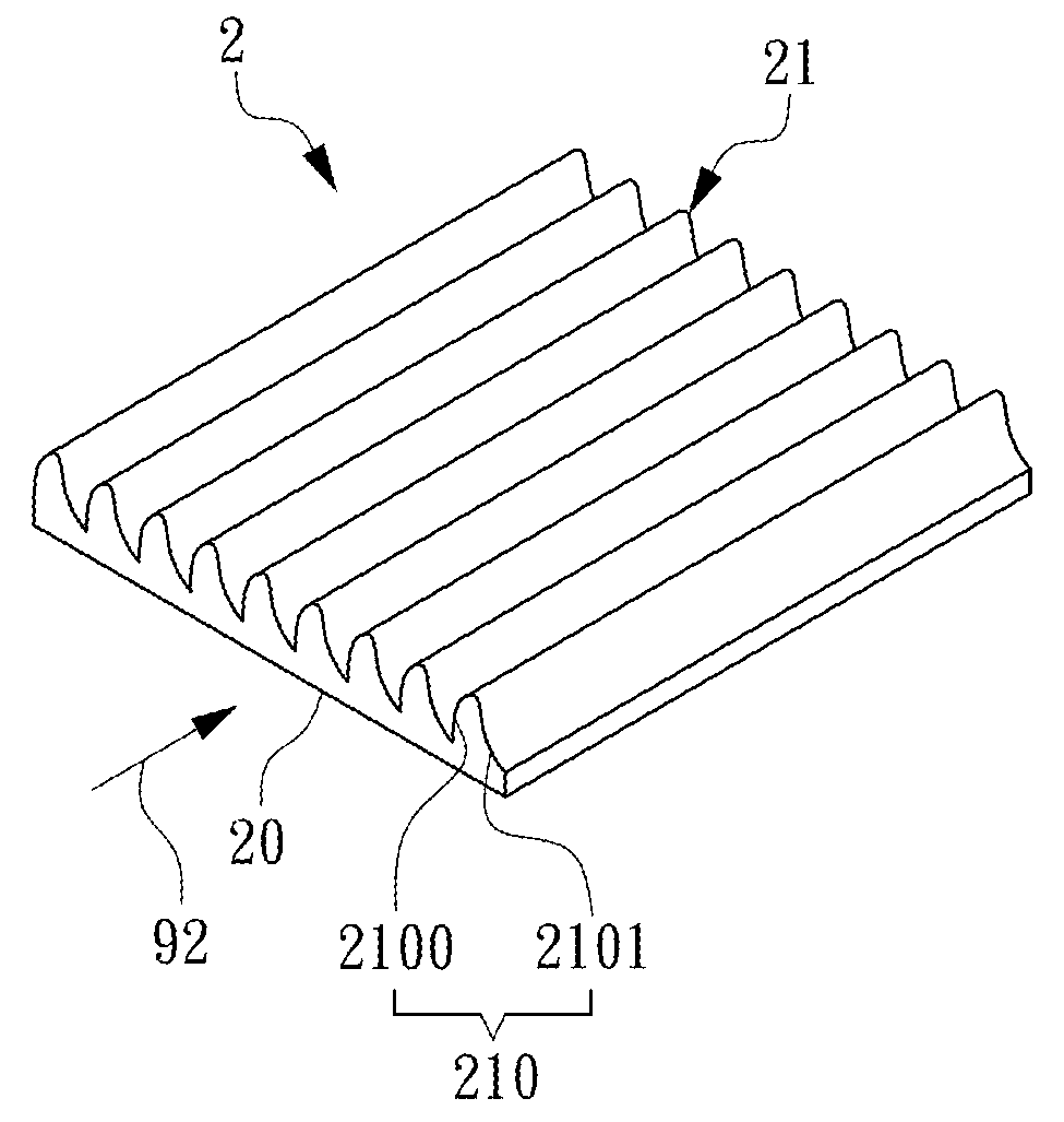
[0025]Please refer to FIG. 2, which is a schematic diagram showing an optical film according to a first embodiment of the invention. In FIG. 2, the optical film 2 is configured with an entrance surface 20 and an exit surface 21. The entrance surface 20 is used for receiving an incident light 92 where it is refracted inside the optical film 2 to form a refracted optical field. The exit surface 21 has a plurality of microstructures 210 formed thereon, in which each microstructure 210 is configured with a first curved surface 2100 and a second curved surface 2101, and by the cooperation of the first and the second curved surfaces 2100, 2101, the refracted optical field is collected to a frontal and normalized view angle of the ex...


PUM


Abstract

An optical film with a plurality of micro structures which are capable of collecting incident light to the frontal and normalized view angle of the optical film for reducing the chance of incident light returning to light guild plate so as to enhance light collecting efficiency is provided in the present invention. In an embodiment, the optical film is combined with a flat light source so as to form a backlight system. By means of the merit of the optical film, the quantities of the optical film can be reduced so that the backlight system can have characteristics of thin thickness and low production cost.

Description

FIELD OF THE INVENTION[0001]The present invention relates to an optical modulation means, and more particularly, to an optical film capable of collect an incident light thereof to its frontal and normalized view angle, and thereby, increasing the brightness of the normal direction of a backlight system using the same.BACKGROUND OF THE INVENTION[0002]Nowadays, it is commonly seen that backlight modules are used in electronic devices with planar displays, which includes devices as small as hand-held palm pilots and as large as big-screen TVs. The design challenge of a backlight module is to generate uniform illumination across the LCD surface and luminance that is high enough to produce good contrast in a day environment, so that most backlight modules had configured therein a brightness enhancement film (BEF) or a dual brightness enhancement film (DBEF) for such light management. It is noted that most optical film used in backlight module, such as a BEF or a DBEF, is thin matte surfa...

Claims


Application Information

Patent Timeline
IPC IPC(8): F21V7/04G02B5/02
CPCG02B5/0221G02B5/045G02B5/0278
Inventor SUN, YI-TINGYU, CHIA-WEIPAO, YU-NAN
Owner IND TECH RES INST
Why Eureka
Try Eureka