
Mixable earphone-microphone device with sound attenuation

a technology of earphones and microphones, applied in the field of mixing earphones and microphones with sound attenuation, can solve the problems of affecting the sensitivity of the human ear, and affecting the sound quality of the natural environment, so as to facilitate the identification and differentiation of each signal and boost the sound level of the natural environmen

Inactive Publication Date: 2009-06-18
PAL AYAN
View PDF9 Cites 16 Cited by
  • Summary
  • Abstract
  • Description
  • Claims
  • Application Information

AI Technical Summary

Benefits of technology

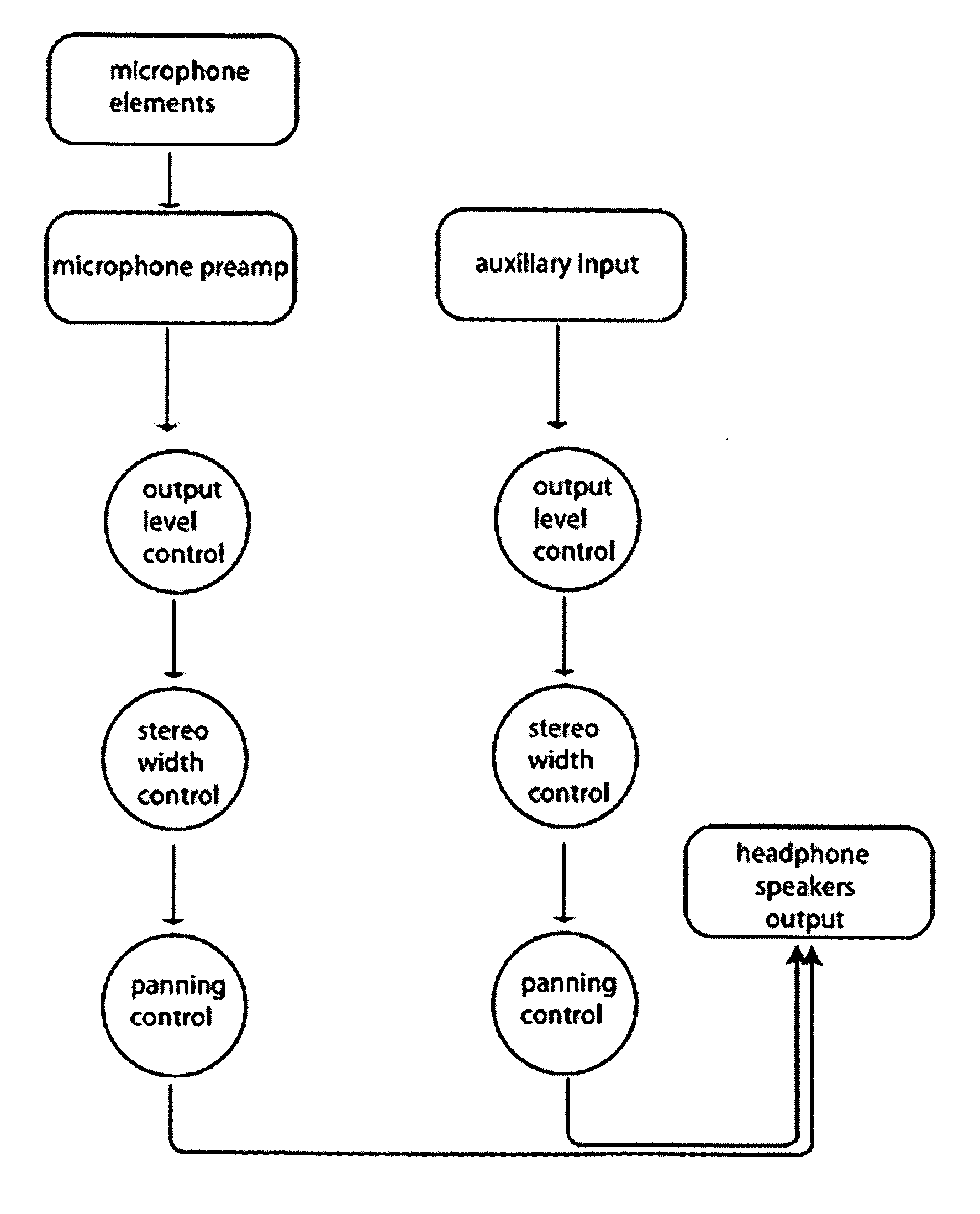
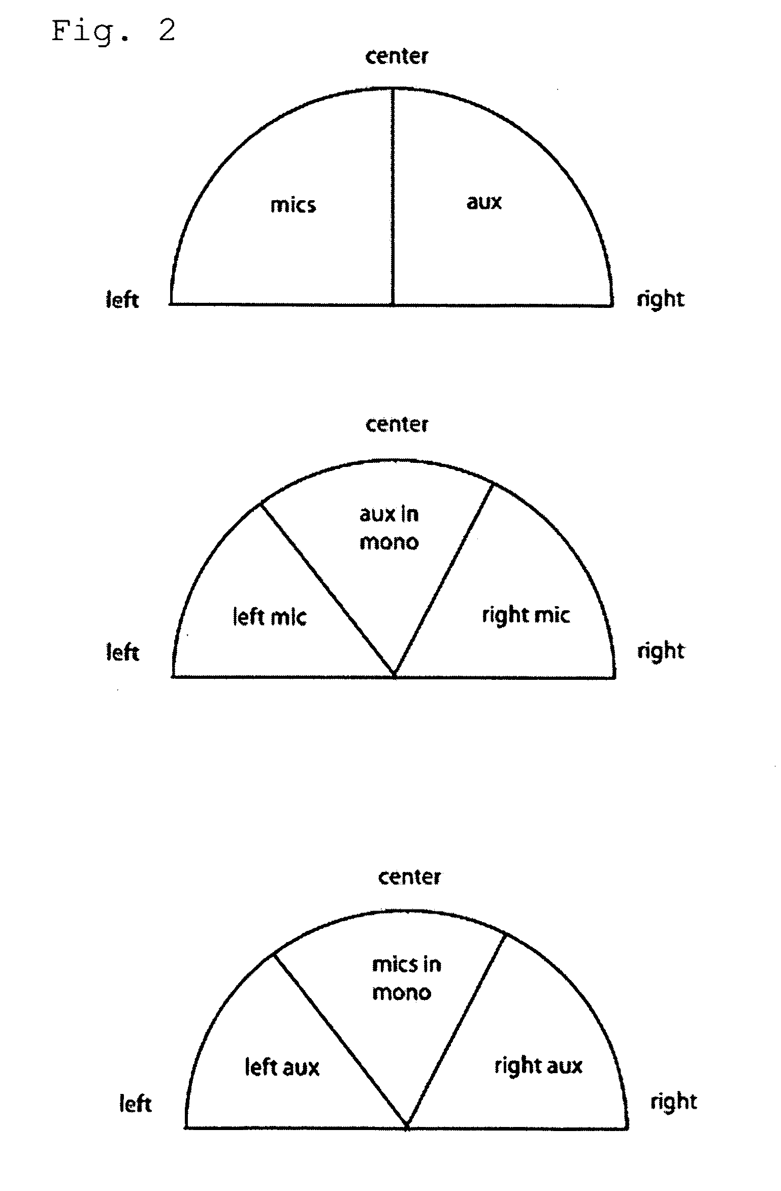
"The patent describes a portable device that can reduce sound levels and capture the user's sound environment using microphones embedded in the device. The device also allows the user to blend in a separate audio source with the user's sound environment. The device can be used as an aid while practicing a musical instrument, a personal monitoring system in a recording studio, or to boost the audio level of the natural environment. The device allows the user to control the placement of the audio signals in the stereo field, making it easier to identify and differentiate each signal when listening to both signals concurrently."

Problems solved by technology

The sensitivity of the human ear is may be reduced, and the organ itself may be damaged by exposure to high levels of sound, including exposure to high amplitude bursts, and exposure to long-term high levels of sound.
While a sound attenuation device does provide an adequate amount of audio level reduction, it also alters the sound quality of natural environment significantly, making the perceived sound muddy and muffled.
Also, it is difficult to monitor external audio sources (for example, a metronome, compact disk, or radio) while wearing hearing protection.
However, these techniques often attenuate or filter out frequencies important to the communication desired to be heard.
In addition, devices that clip or reject some frequencies of the human voice can distort sound quality, and the result can be acoustically unpleasant and interfere with understanding.
Furthermore, none of the previously disclosed devices provide stereo width or panning controls for controlling the stereo image perceived by the used, which allows the user better to distinguish and identify the sounds from the microphones and the auxiliary inputs.

Method used


Image

  • Mixable earphone-microphone device with sound attenuation
  • Mixable earphone-microphone device with sound attenuation
  • Mixable earphone-microphone device with sound attenuation

Examples


example 1

[0060]The device of Example 1 was constructed using the following parts:

[0061]Peltor brand hearing protector ear muffs

[0062]2 Radioshack Electret Microphone Element with Leads, Model: 270-092

[0063]1 set Generic headphones, 1 inch diameter speakers, ⅛″ trs connector

[0064]Velleman MK136 Super Stereo Ear kit

[0065]Rolls MX28 Stereo MINI-MIX VI mixer

[0066]1 digital metronome (not part of the invention, acts as auxiliary audio source)

[0067]2 Hosa CMP153 Y Cable ⅛ Inch TRS to Dual ¼ Inch TS Cable 3 Foot

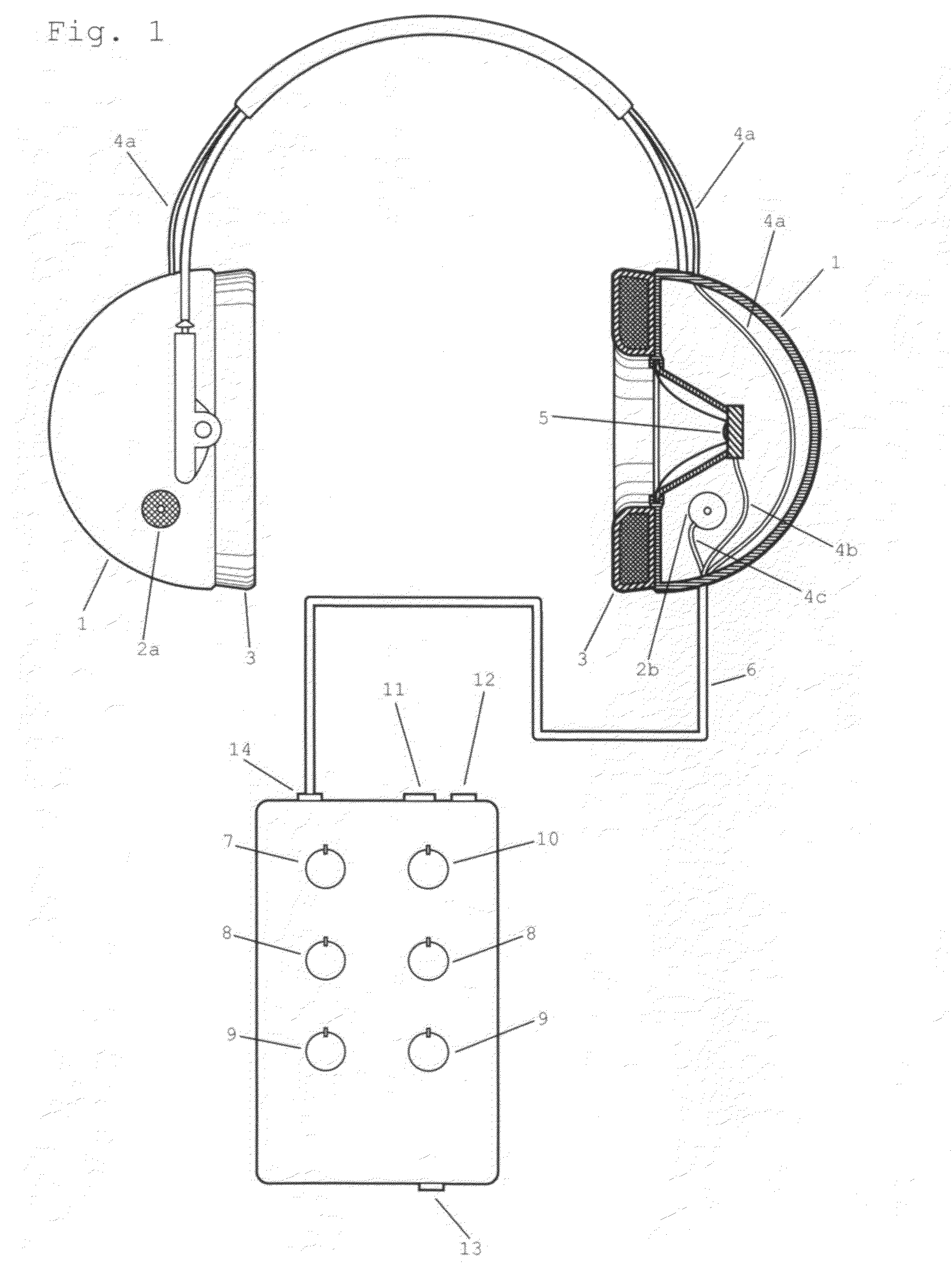
[0068]A 2⅜″ diameter hole was drilled into each earmuff. A microphone capsule was embedded in each hole, and secured adhesive tape. Connection wire was soldered to the leads of each microphone capsule and then soldered directly to the leads of the Velleman MK136 Super Stereo Ear. The headphone speakers were embedded into the inside of the earmuffs using pressure alone. The Velleman MK136 Super Stereo Ear was enclosed in a 2″×3″×4″ metallic project box.

[0069]The headphone output from the Vell...


PUM


Abstract

A portable device that provides sound level attenuation while also providing an acoustic representation of the user's sound environment using microphones attached to, or embedded in, the device, and providing the ability to blend in a user adjustable auxiliary audio source with the user's sound environment signal, whereby placement of the sound signal from both the microphones and the auxiliary input can be adjusted in the stereo field using stereo width and panning controls.

Description

[0001]This application claims the benefit of U.S. Provisional Application No. 61 / 008,176, filed Dec. 18, 2007.BACKGROUND OF THE INVENTION[0002]The sensitivity of the human ear is may be reduced, and the organ itself may be damaged by exposure to high levels of sound, including exposure to high amplitude bursts, and exposure to long-term high levels of sound. Several devices geared toward protecting the ear and its sensitivity from short-term and long-term exposure to high levels of sound have been developed that are well known to one of ordinary skill in the art. Their use varies widely, including, for example, but not limited to, sound attenuation while playing loud musical instruments. For example, playing drums is loud and generally requires some sort of sound attenuation device to achieve comfortable volume levels. The attenuation device is usually either ear plugs or construction style earmuffs (ie. Peltor brand earmuffs).[0003]An example of such as device is described in U.S. ...

Claims


Application Information

Patent Timeline
Patent Type & Authority Applications(United States)
IPC IPC(8): H04R5/02H04R25/00
CPCA61F2011/145A61F11/14A61F11/145
Inventor PAL, AYAN
Owner PAL AYAN
Learn More