Information Display Device And Information Display Method

a technology of information display device and information display method, which is applied in the direction of static indicating device, generating/distributing signals, instruments, etc., can solve the problems of large cost and insufficient effect, and achieve the effect of maintaining the safety of other information display devices

Inactive Publication Date: 2009-06-18
HITACHI OMRON TERMINAL SOLUTIONS CORP
View PDF5 Cites 10 Cited by
  • Summary
  • Abstract
  • Description
  • Claims
  • Application Information

AI Technical Summary

Benefits of technology

[0011]Although a shielding measure can reduce the amount of leakage electromagnetic waves, the shielding measure does not cut off the signal source. To rebuild a building or to remodel a device requires a large cost when a stronger measure is needed due to an improvement in efficiency of an interception device. Since when generating jamming, the maximum is defined by specifications of, such as VCCI, there is a limit to the quantity of jamming which can be generated. Therefore, sufficient effect is not necessarily obtained for the purpose of blocking interception of a leakage electromagnetic wave. The object of the present invention is to reduce or prevent leakage of the original display image by leakage electromagnetic wave interception.

Problems solved by technology

To rebuild a building or to remodel a device requires a large cost when a stronger measure is needed due to an improvement in efficiency of an interception device.
Therefore, sufficient effect is not necessarily obtained for the purpose of blocking interception of a leakage electromagnetic wave.

Method used


Image

  • Information Display Device And Information Display Method
  • Information Display Device And Information Display Method
  • Information Display Device And Information Display Method

Examples


second embodiment

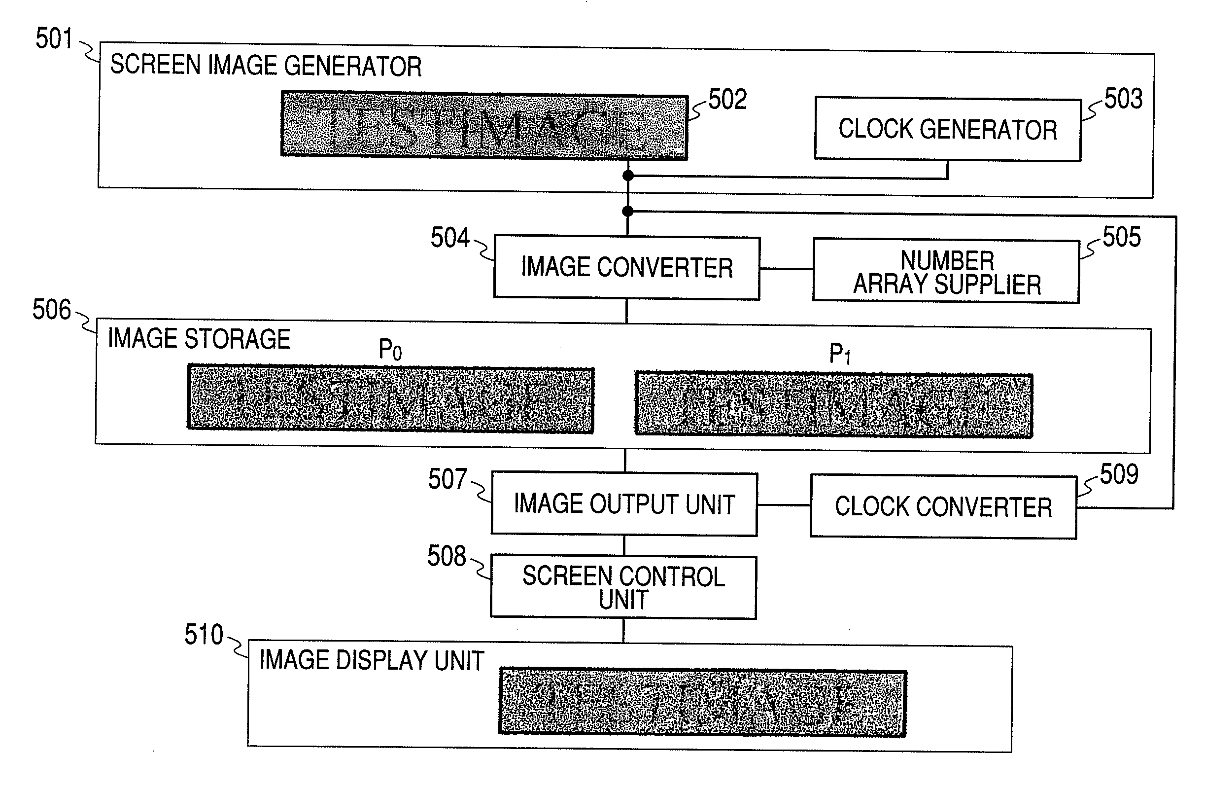
[0083]FIG. 8 shows an embodiment of the information display device according to the present invention. An information display device 801 of this embodiment receives an image I to be displayed to a user and clock information from a screen image generator 802. An image converter 804 generates two converted images P0 and P1, if the image I is received from a screen image generator. The numerical sequence r0 obtained from a number array supplier 803 is used for generation of a converted image. Here, r0 is a set of the random number value of 8 bits, for example, and the size is determined by the resolution of the input image I. If the input image I is an image with the size of XGA, 1024×768=307200 piece numerical values are prepared. These numbers may be generated after receiving the image I, but a sufficient number of numerical values may be generated beforehand, and recorded on a storage. In order to accelerate processing speed, a plurality of number array suppliers may be provided. A ...

third embodiment

[0087]Next, processing is described in the case where the image converter generates three converted images P0, P1, and P2 from one input image I received from the screen image generator. The number array supplier supplies the image converter with a numerical sequence obtained from the random number generator and stored internally. The image converter receives the numerical sequences r0 and r1. The size of r0 and r1 is dependent on the input image I. In the case where the input image I has the size of SVGA, 800×600=480000 pieces of numerical value are made for each r0 and r1 to have.

[0088]Let the numerical values of r0 and r1 be real numbers from 0 to 1. Here, Δ(x, y)=|255−I(x, y)| is assumed. The following relations are assumed or definitions are used. δ(x, y)=min(Δ(x, y), I(x, y)), P0(x, y)=I(x, y)+δ(x, y)*r0(x, y). σ(x, y)=min(Δ(x, y), I(x, y))−δ(x, y)*r0(x, y). And lastly P1(x, y)=I(x, y)+δ(x, y)*r1(x, y), and P2(x, y)=I(x, y)−(δ(x, y)*r0(x, y)+δ(x, y)*r1(x, y)) at the last. Thus...

fourth embodiment

[0090]An embodiment according to the present invention is shown in case that an input-output image is a color image. The case where the two converted images P0 and P1 are generated from the input image I is described.

[0091]An image converter decomposes the inputted color image into three planes of RGB. Next, the numerical sequence used by each plane r0, r1, and r2 are received from the number array supplier. The size of r0, r1, and r2 is determined depending on the resolution of the input image I. If the input image I is in XGA size constituted from 1024×768 dots, then each of r0, r1, and r2 is arranged to have 786432 numerical values, respectively. These values are 8 bits in value, for example, and assumed to be real values from 0 to 1. The pixel value of the coordinates (x, y) in the R plane of the image I is denoted by IR(x, y). Similarly those in the G and B plane are denoted by IG(x, y) and IB (x, y), respectively. As for the image P0, the pixel values of the coordinates (x, y)...


PUM


Abstract

In order to prevent interception of information through leakage electromagnetic waves when transmitting the information using an image display unit, an image converter generates plural converted images, stores the generated converted images in an image storage, an image output unit reads out the converted images from the image storage and transmits the converted images to a screen control unit successively. The screen control unit displays a reception image on an image display unit. The image output unit outputs the converted image group at a high speed, thereby performing a switching display on the image display unit, and shows an image visually equivalent to the input image.

Description

CROSS REFERENCE TO RELATED APPLICATION[0001]This application is a continuation application of U.S. application Ser. No. 12 / 216,736, filed Jul. 10, 2008, the contents of which are incorporated herein by reference.CLAIM OF PRIORITY[0002]The present application claims priority from Japanese patent application JP 2007-204873 filed on Aug. 7, 2007, the content of which is hereby incorporated by reference into this application.FIELD OF THE INVENTION[0003]The present invention relates to information display devices and information display methods, and particularly to a measure against information leakage by TEMPEST (Transient Electro-Magnetic Pulse Emission Surveillance Technology), etc.BACKGROUND OF THE INVENTION[0004]Various electric devices which need calculations and control such as a central arithmetic unit (CPU) mounted on a small microcomputer, a personal computer, or a server have been constructed from a large number of transistors with advancement in function. A transistor is oper...

Claims


Application Information

Patent Timeline
Patent Type & Authority Applications(United States)
IPC IPC(8): G06K9/36G06F7/58G06F1/08G06F3/153G06F21/75G06F21/86G09G3/20G09G5/00
CPCG06F21/84G07F19/20G07F19/201G09G3/2092G09G5/006G06F2221/032G09G2330/021G09G2330/06G09G2340/0414G09G2340/0421G09G2358/00G09G2300/023
Inventor WATANABE, TAKASHISAKO, HIROSHINAGAYOSHI, HIROTOUEMURA, TOSHIRO
Owner HITACHI OMRON TERMINAL SOLUTIONS CORP
Why Eureka
Try Eureka