Apparatus for decomposing suflur-fluorine-containing compound and method thereof

Inactive Publication Date: 2009-06-18
IND TECH RES INST
View PDF8 Cites 1 Cited by
  • Summary
  • Abstract
  • Description
  • Claims
  • Application Information

AI Technical Summary

Benefits of technology

[0011]Accordingly, the invention provides a method for decomposing a gas comprising sulfur-fluorine-containing compound in low temperature which is oxygen-free and has a two steps catalyst process for decomposition. The method comprises: contacting a sulfur-fluorine-containing compound with a first catalyst; decomposing the sulfur-fluorine-containing compound to produce a first decomposition; and contacting the first decomposition with a second catalyst to decompose and produce a second decomposition capable of water-solubility. By using the method, sulfur

Problems solved by technology

Plasma technique for PFCs is only utilized in etching process and its market share is relatively small.
Even wet scrubbing towers are unable to effectively remove the all derivatives produced after bombing.
Moreover, plasma equipment is located close to vacuum equipment resulting in reactor pollution.

Method used


Image

  • Apparatus for decomposing suflur-fluorine-containing compound and method thereof
  • Apparatus for decomposing suflur-fluorine-containing compound and method thereof
  • Apparatus for decomposing suflur-fluorine-containing compound and method thereof

Examples


example 1

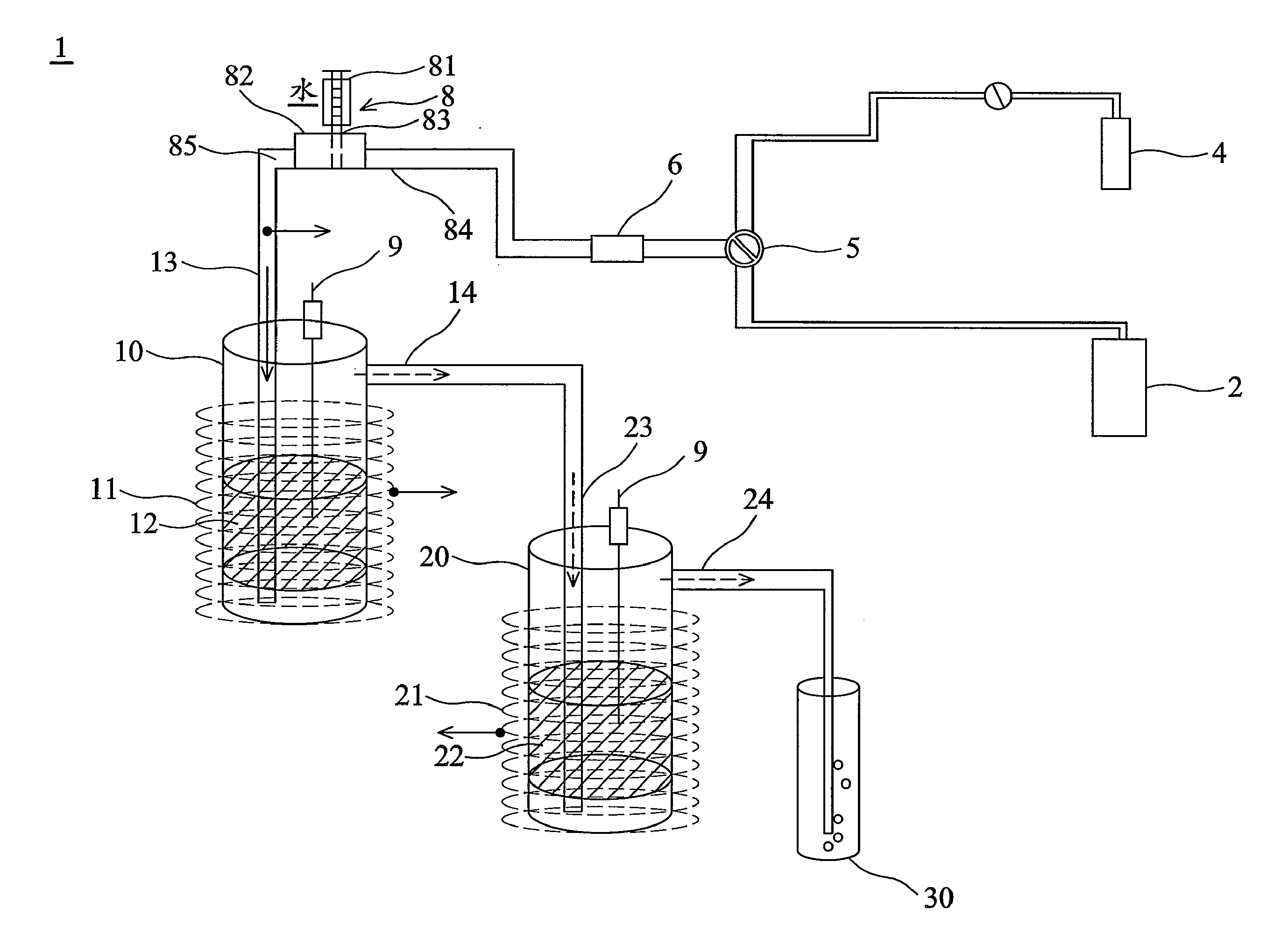
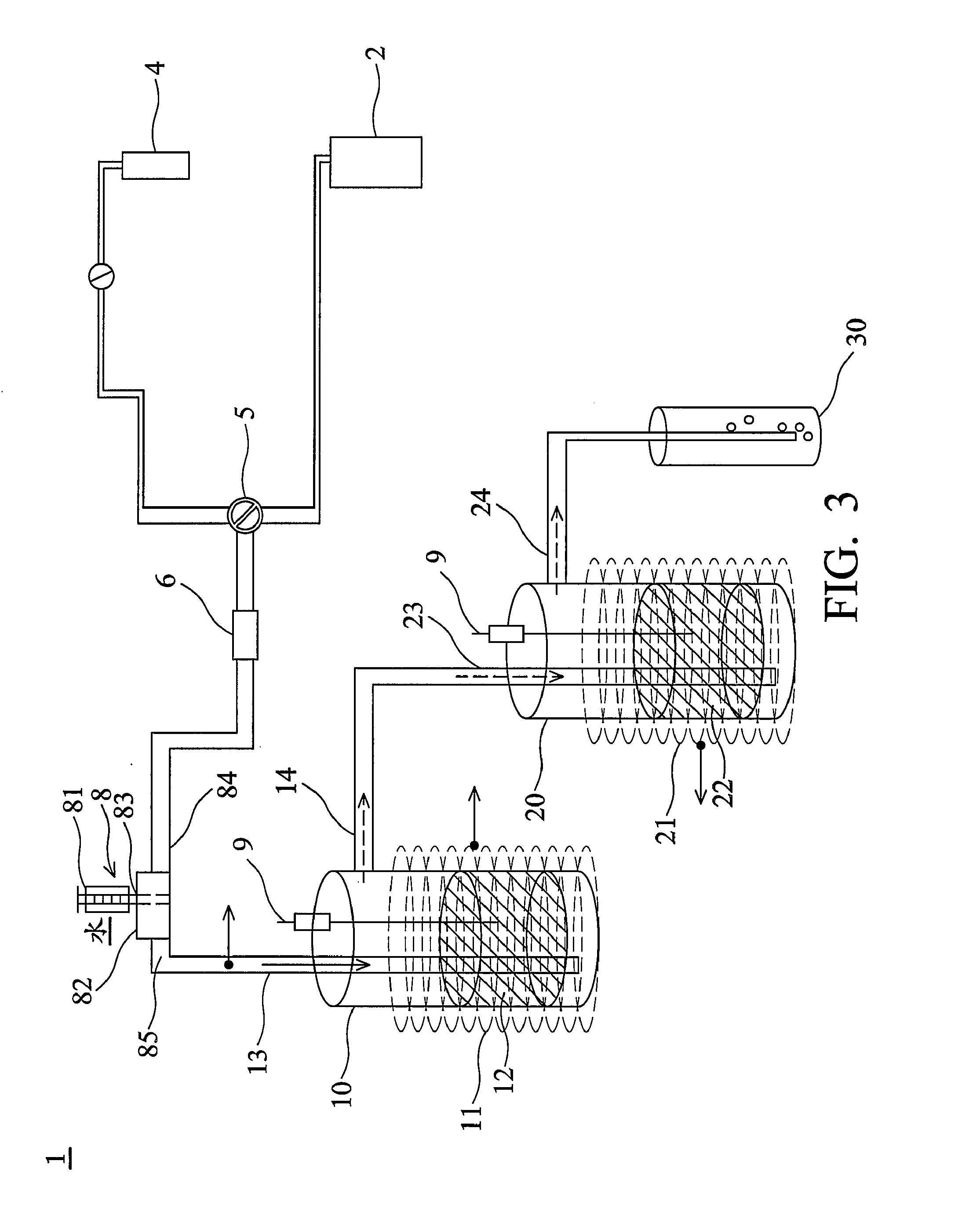
[0049]A gas containing 12161 ppm of SF6 was provided through the sulfur-fluorine-containing compound supply 2 and ratios of the SF6 gas flow to volumes of the first catalyst 12 and the second catalyst 22 were about 100 h−1 (gas hour space velocity; GHSV). The SF6 gas was wet by the wetting equipment 8, in which water was vaporized to be added into the SF6 gas and ratio of vapor volume to the SF6 flow was about 30. The wet SF6 gas was led from the first inlet 13 to the first reactor 10 and was then decomposed into the first decomposition by the first catalyst 12. The first decomposition was led out of the first reactor 10 to the second reactor 20 via the second inlet 23 and was in contact with the second catalyst 22 to decompose and produce the second decomposition comprising the resulting compound such as SO3, HF and SO2F2. Reaction temperatures in the first reactor 10 and the second reactor 20 were both at a temperature of about 680° C. After decomposition, DRE to the SF6 gas was a...

example 2

[0050]A gas containing 11719 ppm of SF6 was provided through the sulfur-fluorine-containing compound supply 2, in which the GHSVs were the same as example 1. The SF6 gas was wet by the wetting equipment 8 and ratio of the added vapor volume to the SF6 flow was about 50. The wet SF6 gas was led from first inlet 13 to the first reactor 10 to decompose and produce the first decomposition. The first decomposition was then led out of the first reactor 10 to the second reactor 20 via the second inlet 23 and was in contact with the second catalyst 22 to decompose and produce the second decomposition. Reaction temperatures of the first reactor 10 and the second reactor 20 were at a temperature of about 580° C. DRE to the SF6 gas in example 2 was about 99.9% and transfer ratio of the residual SO2F2 to SF6 was less than 0.1 mol %. Accordingly, the SF6 gas was completely decomposed into the resulting compound capable of water-solubility through the decomposition apparatus 1. The resulting comp...

example 3

[0051]A gas containing 1073 ppm of SF6 was provided through the sulfur-fluorine-containing compound supply 2, in which the GHSVs were 1216 h−1. The SF6 gas was then wet and ratio of the added vapor to the SF6 gas flow was 120. The wet SF6 gas was led from the first inlet 13 to the first reactor 10 and was decomposed by the first catalyst to produce the first decomposition. Then, the first decomposition was led out of the first reactor 10 to the second reactor 20 via the second inlet 23 and was in contact with the second catalyst 22 to decompose and produce the second decomposition which comprised SO3, HF and SO2F2. Reaction temperatures in the first reactor 10 and the second reactor 20 were at a temperature of about 780° C. DRE to the SF6 gas was about 99.9% and transfer ratio of the residual SO2F2 to SF6 was less than 1.6 mol %. That is, the SF6 gas was completely decomposed into compounds capable of water-solubility through the decomposition apparatus according to the invention. T...


PUM

PropertyMeasurementUnit
Temperatureaaaaaaaaaa
Concentrationaaaaaaaaaa

Abstract

The invention provides a method for decomposing sulfur-fluorine-containing compound and apparatus thereof. Sulfur-fluorine-containing compound is decomposed in two steps, comprising contacting the compound with a first catalyst such as a monometallic catalyst and a second catalyst such as a bimetallic catalyst, and at a low reaction temperature to produce resulting compounds capable of water-solubility. Then, the resulting compounds, namely sulfur- or fluorine-containing compounds, are removed by washing.

Description

BACKGROUND OF THE INVENTION[0001]1. Field of the Invention[0002]The invention relates to a decomposition method for waste gas and decomposition apparatus thereof, and more particularly to a decomposition method for sulfur-fluorine-containing compound and decomposition apparatus thereof.[0003]2. Description of the Related Art[0004]Currently, perfluorochemicals (PFCs) such as CF4, C2F6, C3F8, c-C4F8, CHF3, NF3, and SF6 are utilized in the photoelectricity or semiconductor manufacturing industries, for example, thin-film process, etching process and implantation process. Specifically, SF6 is utilized to clean up equipments for dry-etching and chemical vapor deposition (CVD).[0005]Techniques approved by Intergovernmental Panel on Climate Change (IPPC), with destruction and removal efficiency (DRE) to waste gas of 90%, comprise fueled combustion, plasma and catalytic.[0006]For fueled combustion, CH4 and combustion air are required to generate energy for decomposition of S—F bond by combu...

Claims


Application Information

Patent Timeline
IPC IPC(8): B01D53/48B01D53/68
CPCB01D53/75B01D53/77B01D53/8659B01D2255/206B01D2255/2073B01D2255/20753Y02C20/30B01D2255/20776B01D2255/2092B01D2257/204B01D2257/30B01D2258/0216B01D2255/20761
Inventor YEN, SHAO-IHSU, JUNG-NANLI, SHOU-NAN
Owner IND TECH RES INST
Why Eureka
Try Eureka