Multi-stage in-line cartridge ejector for fuel cell system

a fuel cell system and in-line cartridge technology, applied in electrochemical generators, process and machine control, instruments, etc., can solve the problems of narrow operation range, increase manufacturing costs, and suitable application to fuel cell vehicles, and achieve the effect of increasing the amount of recirculated hydrogen and improving system performan

Active Publication Date: 2009-06-18
HYUNDAI MOTOR CO LTD
View PDF8 Cites 21 Cited by
  • Summary
  • Abstract
  • Description
  • Claims
  • Application Information

AI Technical Summary

Benefits of technology

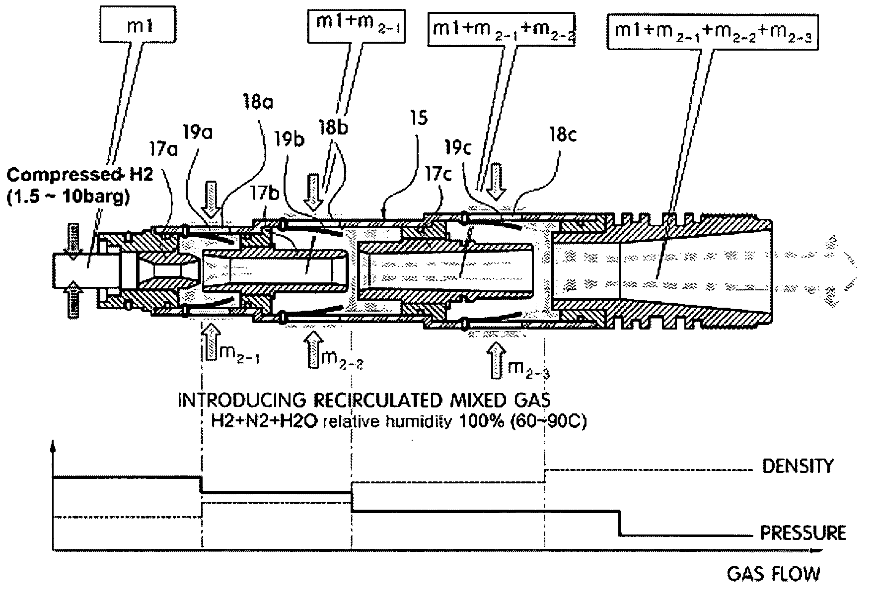
[0019]The present invention has been made in an effort to solve the above-described problems associated with prior art. One object of the present invention is to provide a multi-stage in-line cartridge ejector for a fuel processing system in a fuel cell system, which can improve the system performance by increasing the amount of recirculated hydrogen.

Problems solved by technology

Since conventional blower means has several drawbacks in that it has a complex structure, requires lubrication, and causes noise and vibration, techniques to recirculate the unreacted hydrogen using an ejector means have been proposed.
The ejector means for hydrogen recirculation has advantages in that it has a simpler structure than that of the blower means, it does not require lubrication since rotational elements are not used therein, and it does not cause noise and vibration; however, there is also a problem in that the ejector means has a narrow operation range and thus it is not suitable to apply it to the fuel cell vehicle in which the load is rapidly changed.
However, this approach has some drawbacks in that the plurality of ejectors occupy much space in a vehicle, manufacturing costs increase due to increased number of parts, flux control of the ejectors is not sufficiently accurate due to the difficulty in manipulation of a hydraulically driven needle used therein.
Further, the approach is disadvantageous in that since two or three ejectors are interchanged or switched additional elements such as a device for interchanging or switching the ejectors and a device for preventing reverse flow, thereby inviting a complexity of the structure.
However, it has several drawbacks in that it is expensive and it encounters a pressure loss or leakage problem.

Method used


Image

  • Multi-stage in-line cartridge ejector for fuel cell system
  • Multi-stage in-line cartridge ejector for fuel cell system
  • Multi-stage in-line cartridge ejector for fuel cell system

Examples


Embodiment Construction

[0049]Reference will now be made in detail to the preferred embodiments of the present invention, examples of which are illustrated in the drawings attached hereinafter, wherein like reference numerals refer to like elements throughout. The embodiments are described below so as to explain the present invention by referring to the figures.

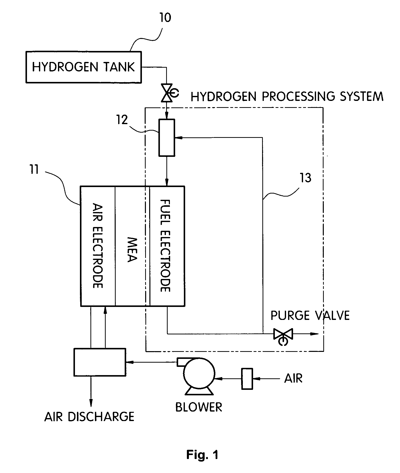
[0050]FIG. 1 is a schematic view showing a fuel processing system in which a multi-stage in-line cartridge ejector in accordance with a preferred embodiment of the present invention is provided.

[0051]As shown in FIG. 1, a fuel processing system (FPS), i.e., a hydrogen supply system, supplies hydrogen from a compressed hydrogen tank 10 to a fuel cell stack 11, and controls the operation of the overall fuel cell system. The FPS includes a low pressure regulator, a multi-stage in-line cartridge ejector 12, various sensors, etc.

[0052]The multi-stage in-line cartridge ejector 12 is disposed between the hydrogen tank 10 and the fuel cell stack 11 and, at ...


PUM

PropertyMeasurementUnit
pressureaaaaaaaaaa
pressureaaaaaaaaaa
diametersaaaaaaaaaa

Abstract

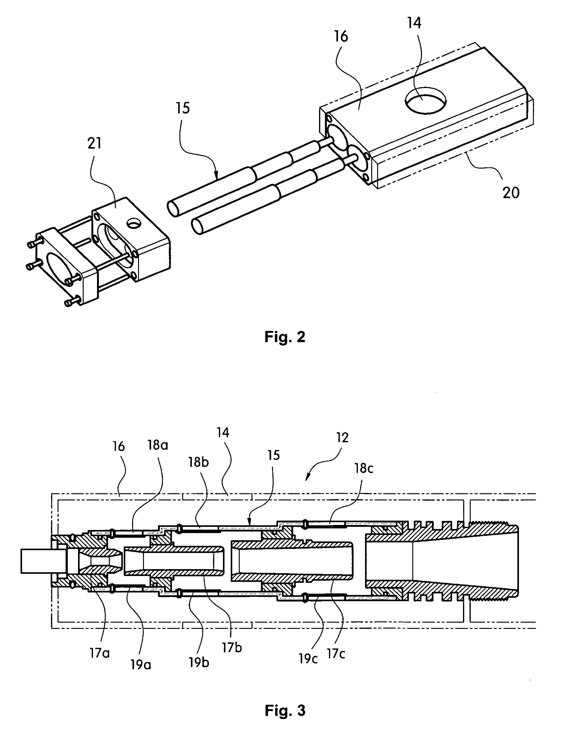
Multi-stage in-line cartridge ejectors for a fuel cell system provided herein comprise: at least one ejector main body for supplying hydrogen, each ejector main body including a plurality of nozzles arranged in line with a predetermined gap, in which the diameters of the respective nozzles become larger from an inlet side of the ejector main body toward an outlet side thereof, and a plurality of sub-inlets formed on an outer surface of the ejector main body to be connected to the gap or gaps between the nozzles; and a housing accommodating the eject main body and including a main inlet for intake of recirculated hydrogen. The multi-stage in-line cartridge ejectors can improve the system performance by increasing the amount of recirculated hydrogen. Moreover, at least one check valve is provided at an intake position of the cartridge ejectors to effectively prevent reverse flow of recirculation hydrogen gas and at least one heater is provided around the cartridge ejectors to improve cold startability.

Description

CROSS-REFERENCE TO RELATED APPLICATION[0001]This application claims under 35 U.S.C. §119(a) the benefit of Korean Patent Application No. 10-2007-0130107 filed Dec. 13, 2007, the entire contents of which are incorporated herein by reference.BACKGROUND[0002](a) Technical Field[0003]The present invention relates to a multi-stage in-line cartridge ejector. More particularly, the present invention relates to a multi-stage in-line cartridge ejector for a fuel cell system, which serves as a hydrogen recirculation blower of a fuel processing system in a fuel cell system to increase the amount of recirculated hydrogen, thus improving the system performance.[0004](b) Background Art[0005]In general, a fuel cell is capable of producing a direct current by converting chemical energy of a fuel gas directly into electrical energy. Unlike other conventional batteries, the fuel cell generates electricity continuously by utilizing fuel and air supplied from the outside.[0006]Hydrogen used as a fuel i...

Claims


Application Information

Patent Timeline
Patent Type & Authority Applications(United States)
IPC IPC(8): H01M8/04
CPCY02E60/50H01M8/04097F04F5/16F04F5/467Y10T137/2564Y10T137/2572Y10T137/7838H01M8/02H01M8/04
Inventor BAN, HYEON SEOKLEE, HYUN JOONNOH, YONG GYUPARK, YONG SUN
Owner HYUNDAI MOTOR CO LTD
Why Eureka
Try Eureka