
Structure of Fixing Planting Base

a planting base and structure technology, applied in the direction of machine supports, furniture parts, turf growing, etc., can solve the problems of increasing the cost and increasing the fixing pieces, and achieve the effect of high construction performance, excellent outlook of planting equipment, and degree of freedom of construction procedures

Inactive Publication Date: 2009-06-25
KYODO KY TEC CORPORATION
View PDF1 Cites 8 Cited by
  • Summary
  • Abstract
  • Description
  • Claims
  • Application Information

AI Technical Summary

Benefits of technology

[0007]The invention is proposed in view of the above-described problems and it is an object thereof to provide a structure of fixing a planting base capable of fixing a planting base with an excellent construction performance without deteriorating an outlook of a planting equipment.
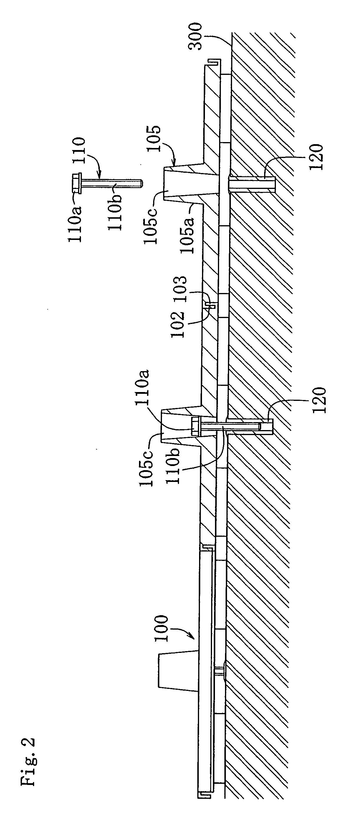
[0015]According to the structure of fixing the planting base of the invention, by arranging the top end of the fixing member at a height substantially the same as that of the top end of the cylinder portion or at inside of the cylinder portion, the cylinder portion of the fixing member can be made to be difficult to be optically recognized by a plant substantially covering the top end of the cylinder portion, and an excellent outlook of a planting equipment can be maintained. Further, by fixing the structure at inside of the cylinder portion isolated from the raising member, a degree of freedom of a construction procedure can be promoted such that the structure is fixed after providing the raising member at, for example, an outer periphery of the cylinder portion, or providing the raising member at the outer periphery of the cylinder portion after fixing the structure by the fixing member or the like, also removal of the structure after having been fixed temporarily is facilitated and a high construction performance is achieved.
[0016]Further, by fixing the structure not on an outer side of the corner portion of the planting base but at inside of the planting base, there is achieved an effect of capable of constituting the structure of low cost formation by reducing a number of pieces of fixing pieces, capable of fixing the structure firmly by high strength without shifting the planting base by an impact and disengaging the structure from being fixed, and capable of restraining a dispersion in a fixing strength of each planting base even when there is an unevenness of the stepped difference is present at the laying face. Further, although according to the structure of being fixed by an outer side of the corner portion, a very delicate adjustment is needed, for example, when the planting tray made of a resin or the like is laid by adhering the base portion to a portion disposed at a corner by carrying out marking, the planting tray is elongated by weather or temperature in construction and a necessary position of installing the base portion differs from a result of the marking, it is necessary to carry out the marking again, the fixing operation can be facilitated with no need of carrying out the marking again.
[0017]Further, by contracting the inner diameter from the top end of the cylinder portion of the planting base to the bottom side, the fixing member of the bolt or the like is easy to be inserted into the cylinder portion and the construction performance can be promoted. Further, the position of inserting the fixing member is made to be able to be set at inside of the cylinder portion by locking the locking portion of the fixing member at the diameter contracting portion at inside of the cylinder portion or locking the locking portion of the fixing member by the locking receive portion at inside of the cylinder portion, the construction performance can be promoted and also the removal is facilitated.
[0018]Further, by fixing the planting base and the water storing portion or the water holding portion to the laying face by arranging the fixing member or the fixing member and the interposing member to the communicated cylinder portions of the planting base and the water storing portion, the water storing portion or the like can be fixed simultaneously with an operation of fixing the planting base, the construction performance can be promoted and the water storing portion or the like can be fixed with the high strength.
[0019]Further, by constituting the interposing member by the slender shape and fixing the plurality of planting bases to the single interposing member, a number of the planting bases can be installed by installing the single interposing member, and the construction performance when the interposing member is provided can be promoted.

Problems solved by technology

Meanwhile, when the planting bases are fixed between the corner portions of the outer sides of the planting bases as described in Patent References 1 through 3, there are brought about drawbacks of (1) a number of pieces of the fixing pieces is increased to increase cost, (2) the planting base is shifted by an impact and is disengaged from the fixing, (3) when an unevenness of a stepped difference or the like is present at the laying face, a stepped difference is brought about at a top face of the planting base at the corner portion, and a fixing strength by the fixing piece is dispersed among the respective planting bases, (4) an outlook is deteriorated by providing a large member optically recognized from a top side of a planting equipment of a drawout preventing member or the like or a member projected considerably to a top side of the planting base.

Method used


Image

  • Structure of Fixing Planting Base
  • Structure of Fixing Planting Base
  • Structure of Fixing Planting Base

Examples


first embodiment

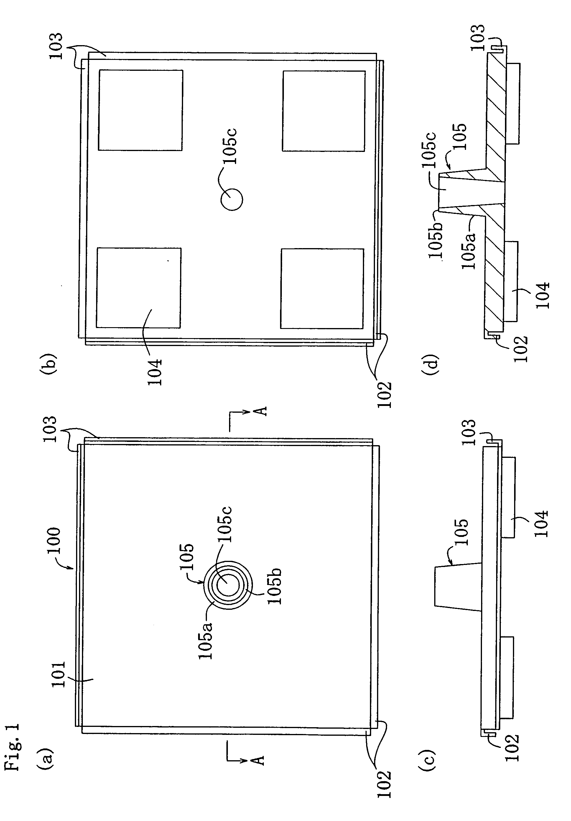
[0064]A structure of fixing a planting base of a first embodiment fixes a planting base 100 to a laying face 300 (refer to FIG. 1 through FIG. 4). As shown by FIG. 1, the planting base 100 includes a bottom plate 101 substantially in a rectangular shape in a plane view thereof constituting a bottom portion and formed with top side engaging connect pieces 102 and bottom side engaging connect pieces 103 at four sides of the bottom plate 101 as engaging connect portions for engaging to connect the planting bases 100 contiguous to each other on four sides of the bottom plates 101. The top side engaging connect pieces 102 are formed substantially in a hook-like shape which is projected from a vicinity of a top face of the bottom plate 101 to an outer side and an end edge of which is bent to be extended to a bottom side in two sides of the bottom plate 101 contiguous to each other on one side, and the bottom side engaging connect pieces 103 are formed substantially in a hook-like shape wh...

second embodiment

[0073]A structure of fixing a planting base according to a second embodiment will be explained in details of a portion thereof which differs from the first embodiment.

[0074]In the planting base 100 according to the second embodiment, as shown by FIG. 6, the support leg 104 is formed by a shape of a rectangular parallelepiped higher than that of the first embodiment, a locking receiving portion 105d of a horizontal face is formed at a predetermined position at inside of the hole portion 105c in the diameter of the inner peripheral face of which is gradually contracted from the upper end face 105b, a through hole 105e opened at a center of the locking receiving portion 105d and penetrated to the bottom side by substantially the same diameter is formed, and the diameter of the hole portion 105c is narrowed in a stepped shape to the bottom side. Although the opening portion at the upper end of the cylinder portion 105 is larger than the bolt head portion 110a and can insert the head por...

third embodiment

[0079]Next, a structure of fixing a planting base of a third embodiment will be explained in details of a portion which differs from the first and the second embodiments.

[0080]As shown by FIG. 7, a planting base of the third embodiment is a planting container 140 substantially in a box-like shape which includes a bottom plate 141 and a side wall 142 and a top face of which is opened. The side wall 142 of the planting container 140 is formed with an inwardly recessed portion 143 from a middle to a lower portion thereof, further, the bottom plate 141 is provided with a plurality of support legs 144 in an L-like shape or an I-like shape in a bottom view thereof formed by being projected to the bottom side, a plurality of water passing and air passing holes 145 constituting holes in a slit-like shape capable of draining extraneous water to a water storing tray 150, mentioned later, and sending air to a root of the plant 107, and water absorbing projected portions 146 formed to project t...


PUM


Abstract

A structure of fixing a planting base 100 supporting a planted raising member 106 by a bottom plate 101 to a laying face 300, provided with a cylinder portion 105 which is projected from the bottom plate 101 of the planting base 100 to a top side and top and bottom of which are opened in which an inner diameter is gradually contracted from a top end to a bottom side, a bolt 110 constituting a fixing member is inserted to the cylinder portion 105, the bolt 110 is screwed to and fixed by an anchor holder 120 of the laying face 300 until a position at which a bolt head portion 110a is brought into contact with and caught by an inner face of the cylinder portion 105, and a top face of the bolt head portion 110a is arranged at a height the same as that of a top end of the cylinder portion 105, or arranged at inside of the cylinder portion 105. The planting base can be fixed with an excellent construction performance without deteriorating an outlook of a planting equipment.

Description

TECHNICAL FIELD[0001]The present invention relates to a structure of fixing a planting base for fixing a planting base supporting a planting portion at a bottom portion thereof to a laying face.BACKGROUND ART[0002]Although an urban area of the present age society is lack of nature, in order to compensate for lack of nature to meet a desire of human being for the nature, a greening measure in the urban area is achieved by providing a planting equipment of artificially greening, for example, a rooftop of a building, a roof of a building of a folded plate roof or the like, a veranda, a terrace or the like. Although various planting equipments have been proposed, there is known a planting equipment using a planting base for supporting a planting portion at a bottom portion thereof as one thereof. According to the planting equipment, a light-weighted planting base is used in view from a load resistance of a building, and therefore, it is preferable to fix the planting base to the laying ...

Claims


Application Information

Patent Timeline
Patent Type & Authority Applications(United States)
IPC IPC(8): A01G1/00A01G9/02B65D19/38
CPCE04D11/002A01G1/007Y02B80/32E04D11/005Y02A30/254A01G9/033
Inventor YOSHIDA, MINORUKUMURA, KAZUOYOSHIOKA, TAKAHARUUEDA, YASUYUKI
Owner KYODO KY TEC CORPORATION
Learn More