
Method and apparatus for detecting a stroke of a 4-cycle internal combustion engine, based on changes in rotary engine speed

a technology of internal combustion engine and speed change, which is applied in the direction of engine testing, structural/machine measurement, electrical control, etc., can solve the problems of engine peak performance, inability to perform manifold vacuum, and inability to detect a stroke based on such intake manifold vacuum, etc., and achieve the effect of reducing the rate of change of rotary engine speed

Inactive Publication Date: 2009-06-25
HONDA MOTOR CO LTD
View PDF14 Cites 10 Cited by
  • Summary
  • Abstract
  • Description
  • Claims
  • Application Information

AI Technical Summary

Benefits of technology

[0026]The rate of change of the rotary engine speed after the compression top dead center is greater than the rate of change of the rotary engine speed after the exhaust top dead center. Accordingly, in the present invention, the detection between the compression top dead center and the exhaust top dead center is performed by making use of the difference the in rate of change, and the detection between the power stroke and the intake stroke is performed based on the detection result of the compression top dead center and the exhaust top dead center.
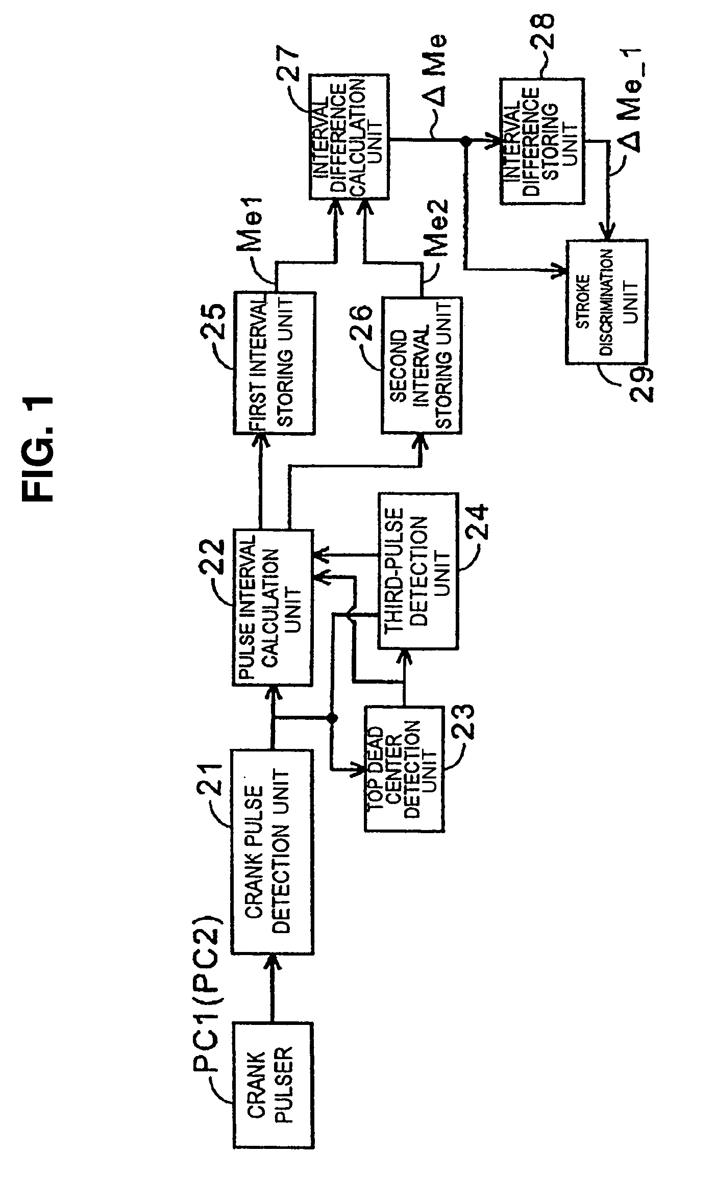
[0027]The difference in rate of change can be determined by detecting the change quantities of the crank-pulse time intervals at two predetermined positions before and after the compression top dead center with respect to two continuous top dead centers and by deciding which one of the change quantities detected with respect to both top dead centers is greater.
[0028]According to the first through fifth aspects of the present invention, the stroke detection can be performed by sensing the rotary engine speed (or the crank-pulse time interval which represents the rotary engine speed). Hence, also where the stroke detection cannot be performed using the intake manifold vacuum, particularly in an operation region where the throttle opening is large and the change of the intake manifold vacuum is small, the stroke detection can be performed based on only an output of the crank angle sensor without using the cam pulser.
[0029]According to the sixth aspect of the present invention, it is possible to selectively use the stroke detection apparatus based on the rotary engine speed and the intake manifold vacuum corresponding to the throttle opening. Hence, the stroke detection can be performed in a large operational region without using the cam pulser.
[0030]For a more complete understanding of the present invention, the reader is referred to the following detailed description section, which should be read in conjunction with the accompanying drawings. Throughout the following detailed description and in the drawings, like numbers refer to like parts.

Problems solved by technology

However, there may be a situation in which the stroke detection based on such intake manifold vacuum cannot be performed.
Hence, the stroke detection based on the intake manifold vacuum cannot be performed, whereby there may be a possibility that the engine cannot provide peak performance.
Hence, the method is not applicable to various starting variations such as kick starting or cell starting, whereby there may be a possibility that the stroke detection cannot be performed in such conditions.
Hence, there exists a possibility that the change of an angular velocity sufficient for performing the stroke detection cannot be acquired.

Method used


Image

  • Method and apparatus for detecting a stroke of a 4-cycle internal combustion engine, based on changes in rotary engine speed
  • Method and apparatus for detecting a stroke of a 4-cycle internal combustion engine, based on changes in rotary engine speed
  • Method and apparatus for detecting a stroke of a 4-cycle internal combustion engine, based on changes in rotary engine speed

Examples


Embodiment Construction

[0037]It should be understood that only structures considered necessary for illustrating selected embodiments of the present invention are described herein. Other conventional structures, and those of ancillary and auxiliary components of the system, will be known and understood by those skilled in the art.

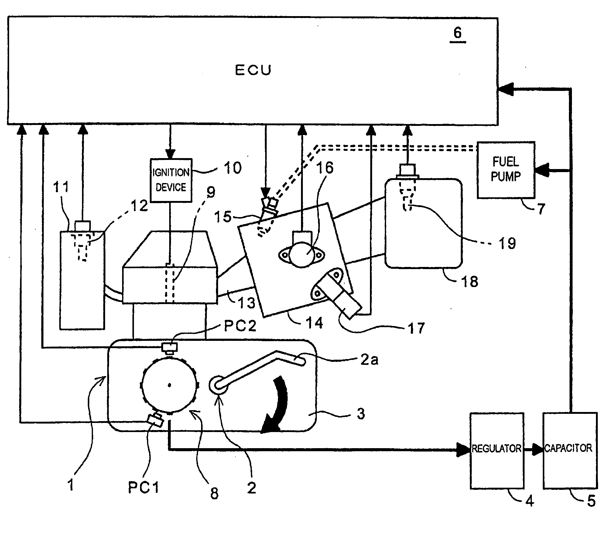
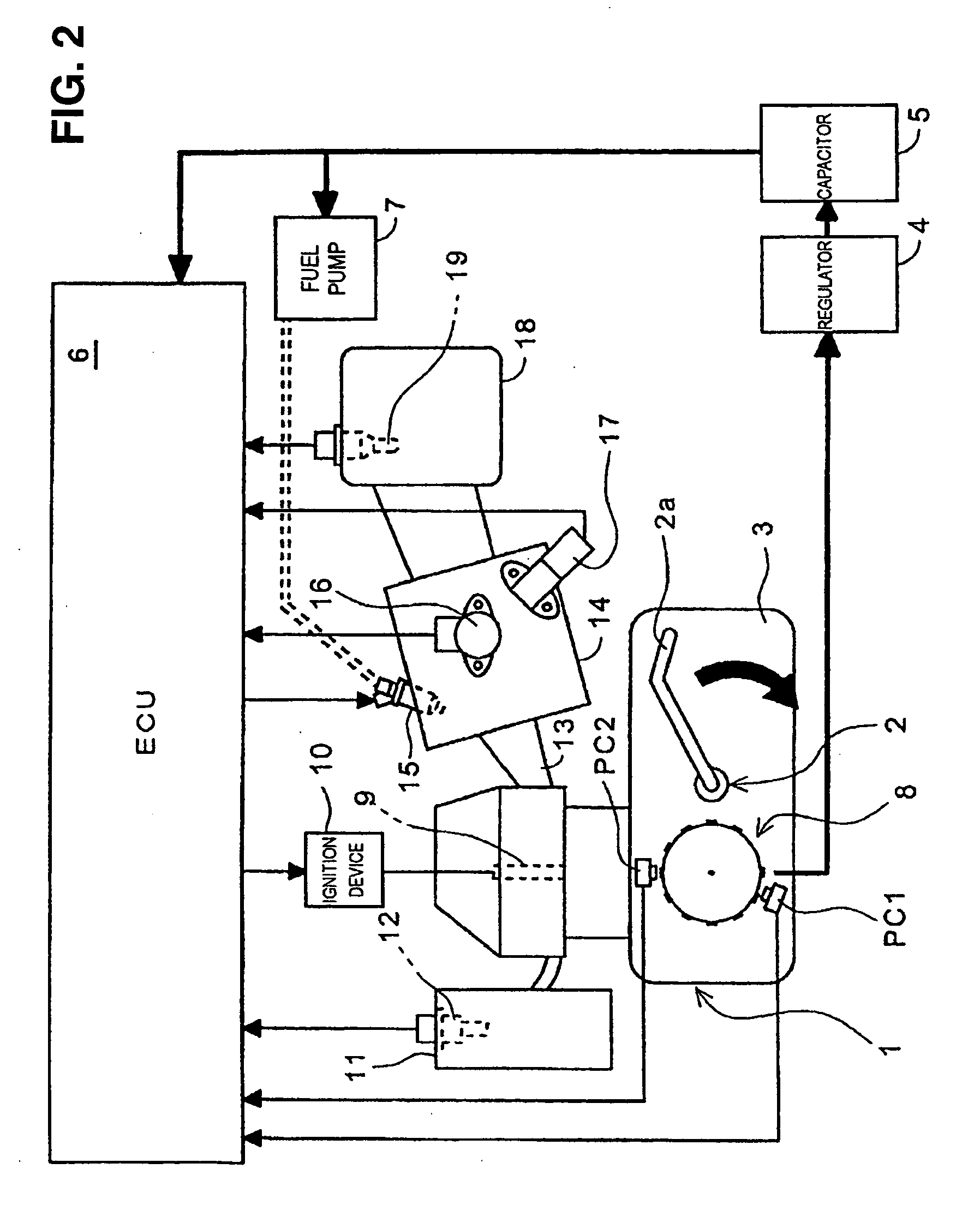
[0038]Hereinafter, an illustrative embodiment of the present invention is explained in conjunction with drawings. FIG. 2 is a block diagram showing a system configuration of an engine control apparatus including a stroke detection apparatus according to an illustrative embodiment of the present invention.

[0039]In the embodiment shown in FIG. 2, an engine 1 is a 4-cycle, single-cylinder internal combustion engine. The engine 1 includes an intake / exhaust valve assembly (not shown). The engine 1 also includes a kick-starter 2, having a kick pedal 2a, as a manual starting system. An operator of a vehicle having the engine 1 can start the engine 1 by rotating a crankshaft (not shown) b...


PUM


Abstract

A stroke detection apparatus performs a stroke detection of 4-cycle engine based on a rotary engine speed when a throttle opening is large. A first crank-pulse time interval between a crank pulse inputted before a top dead center by 30°, and a crank pulse of the top dead center is measured by a pulse-interval calculation unit, and at the same time, a second crank-pulse time interval between a crank pulse inputted after the top dead center by 60° and a crank pulse inputted after the top dead center 90° is measured. An interval difference calculation unit calculates time-interval difference by subtracting the second crank-pulse time interval from the first crank-pulse time interval, for two continuous top dead centers. A stroke detection unit determines whether two top dead centers are a compression top dead center or an exhaust top dead center based on magnitudes of the time-interval differences.

Description

CROSS-REFERENCE TO RELATED APPLICATIONS[0001]The present application claims priority under 35 USC §119 based on Japanese patent application No. 2007-328664, filed on Dec. 20, 2007. The entire subject matter of this priority document, including specification, claims and drawings, is incorporated by reference herein.BACKGROUND OF THE INVENTION[0002]1. Field of the Invention[0003]The present invention relates to method and apparatus for detecting a stroke of a 4-cycle engine. More particularly, the present invention relates to method and apparatus of the type described, which enhances accuracy of stroke detection in an operational region having a low rotary engine speed and a large throttle opening.[0004]2. Description of the Background Art[0005]There is a known 4-cycle internal combustion engine having a control device (including stroke detection apparatus) for determining optimum ignition timing. This type of known engine is described, for example, in published Japanese patent docume...

Claims


Application Information

Patent Timeline
Patent Type & Authority Applications(United States)
IPC IPC(8): G01M15/04
CPCF02D41/009F02D2200/0406F02D2200/0404F02D41/1497
Inventor MACHIDA, KENICHIOUCHI, KATSUHIRO
Owner HONDA MOTOR CO LTD
Learn More