Image capturing module, method for manufacturing the image capturing module, and electronic information device

a technology of image capturing and module, applied in the field of image capturing modules, can solve the problems of large number of parts, loose measurement accuracy in x and y directions, difficult manufacturing, etc., and achieve the effects of finer assembling, accurate fixing, and improved parts accuracy

Inactive Publication Date: 2009-06-25
SHARP KK
View PDF5 Cites 66 Cited by
  • Summary
  • Abstract
  • Description
  • Claims
  • Application Information

AI Technical Summary

Benefits of technology

[0065]The structure for determining the position of the holder member to the substrate can be changed into a simple structure with a significantly smaller number of parts of the image capturing module compared to the prior art by directly placing a height-direction position determining section of the holder member to the surface of the sensor chip, which functions as an image capturing chip, and determining the position. With respect to the upper surface of the sensor chip, the lens fixed to the holder member can be positioned such that the distance in the vertical direction (z axial direction) between the lens and the sensor chip is accurately fixed. As a result, the accuracy for the parts, the assembly and the implementation are improved, thereby achieving a focus-adjustment free image capturing module. In this structure, the surface of the sensor chip and the height direction determining section are not adhered to each other and there is no adhesive interposing therebetween. The distance does not significantly vary ranging between 5 to 25 μm due to the adhesive layer, thereby achieving finer assembling with finer accuracy.
[0066]In addition, the structure for determining the position of the holder member to the substrate can be changed into a simple structure with significantly smaller number of parts of the image capturing module compared to the prior art by directly placing three points of the height direction position determining section of the holder member to the surface of the sensor chip, which functions as an image capturing chip and determining the position. With respect to the upper surface of the sensor chip, the lens fixed to the holder member can be positioned such that the distance in the vertical direction (z axial direction) between the lens and the sensor chip is accurately fixed. In this case, the three points of the height direction position determining section all certainly touch the upper surface of the sensor chip without floating in midair, thereby achieving a finer accuracy for determining the position in the height direction. As a result, the accuracy for the parts, the assembly and the implementation are improved, thereby achieving a focus-adjustment free image capturing module. Further, at the assembling, the substrate having a sensor chip attached thereon is accurately set by mating with position determining pins, and the holder member integrated with a lens is positioned and attached to the sensor chip and substrate, which are set with high accuracy, by an automated assembling apparatus, so that the occurrence of offset in a plane direction (X and Y directions) can be controlled to its minimum and the position can be determined with high accuracy. Further, according to a new structure of the present invention, the sensor chip fixed to the substrate is sealed by the holder member integrated with a lens such that the inside is covered from the top, so that the leakage of light will not occur from the outside to the inside. Since this is a sealed structure, no dust enters the inside and no dust adheres to an inside image capturing area of the sensor chip. Therefore, the quality of the image can be improved.
[0067]The holder member integrated with a lens is positioned and attached to the substrate having a sensor chip attached thereon by the automated assembling apparatus that recognizes a plane image of an appropriate sensor chip, so that the occurrence of an offset in a plane direction (X and Y directions) can be controlled at its minimum and the position can be determined with high accuracy.
[0068]Further, according to a new structure of the present invention, the sensor chip fixed to the substrate is sealed by the holder member integrated with a lens such that the inside is covered from the top, so that the leakage of light will not occur from the outside to the inside. Since this is a sealed structure, no dust enters the inside and no dust adheres to an inside image capturing area of the sensor chip. Therefore, the quality of the image can be improved.
[0069]According to the present invention with the structure described above, the height direction position determining section is directly placed on the upper surface of the image capturing chip as a reference surface of the holder member to determine the position in the height direction. Some variation factors may be conceivable with respect to the accuracy of assembling a focusing lens to the holder member and the accuracy of casting the holder member. However, the present invention has the smaller number of parts compared to the conventional structures and has a simple structure. Therefore, the man-hours of assembling can be reduced and the assembling accuracy can be improved, achieving no needs for focus adjustment. In this case, the three points of the height direction position determining section all certainly touch the upper surface of the sensor chip without floating in midair, thereby achieving a finer accuracy for determining the position in the height direction. Further, the surface of the sensor chip and the height direction determining section are not adhered to each other and there is no adhesive interposing therebetween. Therefore, the assembly can be conducted with more accurate distance between the lens and the sensor chip, achieving no needs for focus adjustment.

Problems solved by technology

However, when the inside of the circle inside the space d passes light and the outside of the circle is shielded from light, as illustrated in FIGS. 8(a) and 8(b), it is difficult, in terms of manufacturing, to shield only the portion where the leg extends in a lower direction in order to prevent light from the side direction from entering the sensor section 102a.
If the room is too large, the measurement accuracy in the X and Y directions will be loose.
In manufacturing them, there are great numbers of parts and the structures are complicated.
Further, there are many items to be controlled, a great deal of man-hours are also required, and the accuracy for assembling tends to have a problem.
As a result, the number of the parts will increase and the structure will be complicated.
Therefore, there are many items to be controlled, a great deal of man-hours are also required, and the accuracy for assembling tends to have a problem.
The adhesive layers largely vary from 5 to 25 μm in thickness, and therefore, the distance cannot be accurately determined between the lens in the holder and the image capturing element chip.
It is not possible to omit the optical adjustment for improving the yield and the light focusing efficiency.

Method used


Image

  • Image capturing module, method for manufacturing the image capturing module, and electronic information device
  • Image capturing module, method for manufacturing the image capturing module, and electronic information device
  • Image capturing module, method for manufacturing the image capturing module, and electronic information device

Examples


embodiment 1

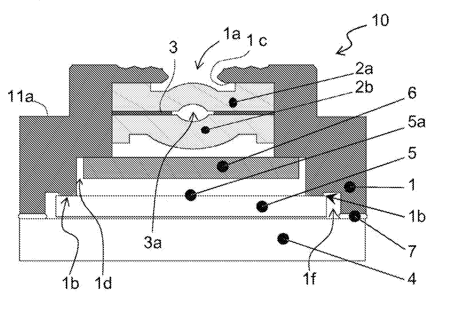
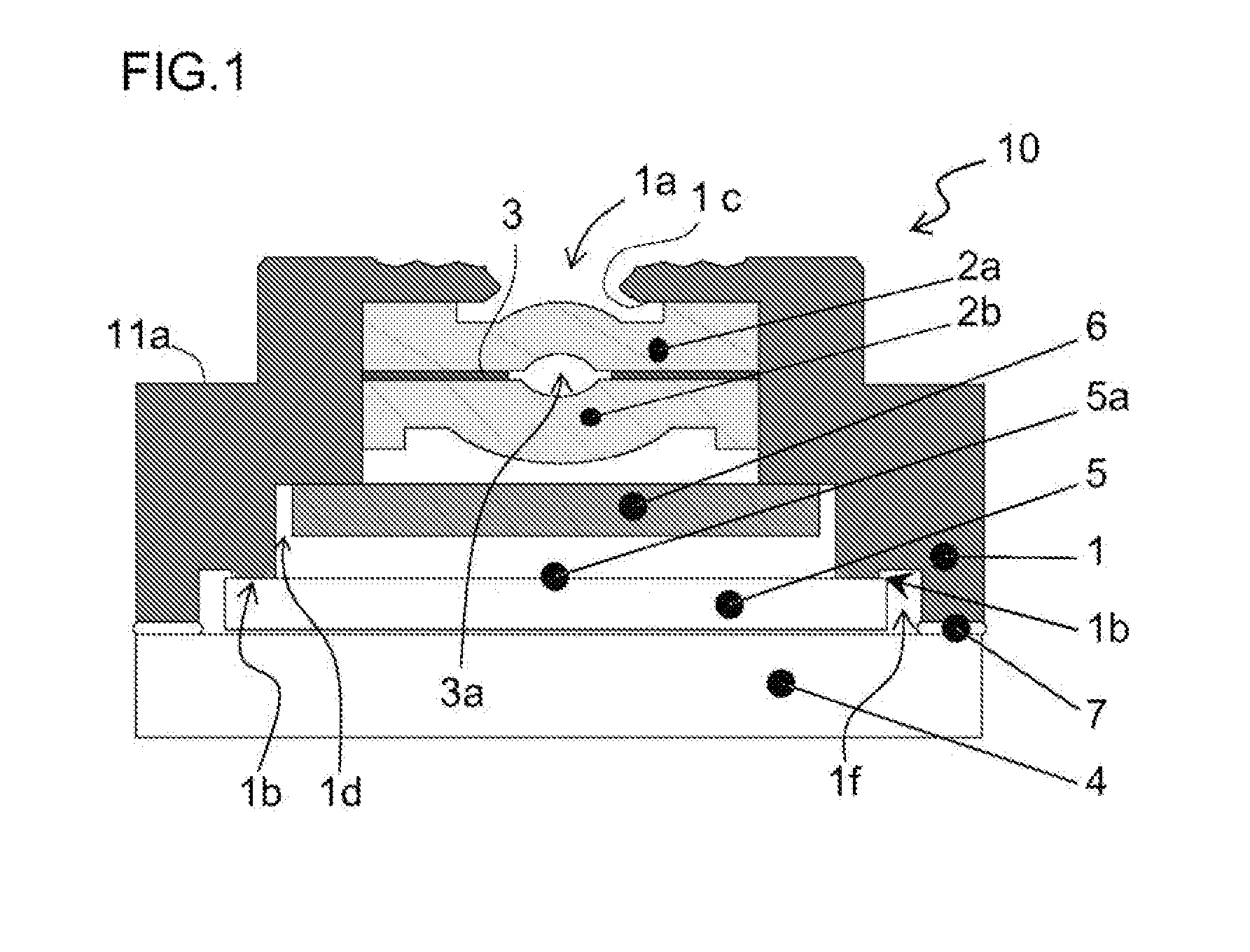
[0109]FIG. 1 is a longitudinal cross sectional view schematically illustrating an exemplary essential structure of an image capturing module according to Embodiment 1 of the present invention.

[0110]In FIG. 1, an image capturing module 10 according to Embodiment 1 includes: a holder member 1 functioning as a dustproof case; a first focusing lens 2a and a second focusing lens 2b vertically accommodated in the holder member 1; a light shielding film 3 provided in between the first focusing lens 2a and the second focusing lens 2b; a substrate 4; a sensor chip 5 provided on the substrate 4 and for functioning as a solid-state image capturing chip; an IR cut filter 6 fixed to a first step portion 1d inside the holder member 1 and positioned by traversing between the second focusing lens 2b and the sensor chip 5; and an adhering section 7 for adhering a bottom surface of an outer wall of the holder member 1 to the substrate 4.

[0111]The dustproof holder member 1 has a structure to cover the...

embodiment 2

[0125]In Embodiment 1 described above, a case has been described where the height direction position determining section 1b with a flat surface of the holder member 1 is directly placed on the upper surface of the sensor chip in order to accurately determine the distance between the lens fixed to the holder member 1 and the upper surface of the sensor chip 5. In Embodiment 2, a case will be described where the height direction position determining section 1b is received as a shape of a point (circular shape or ellipse shape) on the upper surface of the sensor chip 5, instead of being received as the shape of a flat surface.

[0126]FIG. 4 is a longitudinal cross sectional view schematically illustrating an exemplary essential structure of an image capturing module according to Embodiment 2 of the present invention.

[0127]In FIG. 4, an image capturing module 10A according to Embodiment 1 includes: a holder member 1A functioning as a dustproof case; a first focusing lens 2a and a second f...

embodiment 3

[0131]In Embodiment 2 described above, the height direction position determining section (protruding portion) in a pointed shape (circular shape or ellipse shape) has been described. In Embodiment 3, the number of the height direction position determining section in a pointed shape (circular shape or ellipse shape) will be described.

[0132]FIG. 5 is a plan view schematically illustrating a positional relationship between an upper surface of a sensor chip and a height direction position determining section in a pointed shape in an image capturing module according to Embodiment 3 of the present invention. Note that the same reference number is denoted to a constituent member having the same function or effect as a constituent member in FIG. 1 or 4.

[0133]In FIG. 5, the positional relationship between the upper surface of the sensor chip 5 and three points of the height direction position determining section is such that the three points are positioned avoiding the image capturing area 5...


PUM

PropertyMeasurementUnit
thicknessaaaaaaaaaa
distanceaaaaaaaaaa
thicknessaaaaaaaaaa

Abstract

An image capturing module according to the present invention includes a holder member, which accommodates therein a focusing lens for forming an image of a subject light on an image capturing chip attached on a substrate and is attached to the substrate to cover the image capturing chip, where the holder member is directly supported on a surface of the image capturing chip.

Description

[0001]This nonprovisional application claims priority under 35 U.S.C. §119(a) to Patent Application No. 2007-297306 filed in Japan on Nov. 15, 2007, Patent Application No. 2007-300976 filed in Japan on Nov. 20, 2007, and Patent Application No. 2008-108373 filed in Japan on Apr. 17, 2008, the entire contents of which are hereby incorporated by reference.BACKGROUND OF THE INVENTION[0002]1. Field of the Invention[0003]The present invention relates to an image capturing module, in which an image capturing element having a plurality of light receiving sections for performing photoelectric conversions on and capturing image light from a subject and a lens for forming an image of incident light on the image capturing element are modularized (integrated); a method for manufacturing the image capturing module; and an electronic information device, such as a digital camera (e.g., digital video camera and digital still camera), an image input camera (e.g., car-mounted camera), a scanner, a fac...

Claims


Application Information

Patent Timeline
Patent Type & Authority Applications(United States)
IPC IPC(8): H04N5/225H04N5/232B32B37/00
CPCG02B7/021G03B17/00H04N5/2253Y10T156/10H04N5/2257H04N5/23212H04N5/2254H04N23/54H04N23/57H04N23/55
Inventor FUKAMACHI, TAKAYUKIHIROOKA, SHOHGO
Owner SHARP KK
Why Eureka
Try Eureka