Ferromagnetic tunnel junction device, magnetic head, and magnetic storage device

a tunnel junction and magnetic head technology, applied in the field of ferromagnetic tunnel junctions, can solve the problem of low mr ratio

Inactive Publication Date: 2009-06-25
FUJITSU LTD
View PDF3 Cites 48 Cited by
  • Summary
  • Abstract
  • Description
  • Claims
  • Application Information

AI Technical Summary

Benefits of technology

[0008]According to an aspect of an embodiment, a ferromagnetic tunnel junction device includes: a first pinned magnetic member including a ferromagnetic material having a boron atom, the magnetization direction of the first pinned magnetic member being capable of being pinned; a second pinned magnetic member including a ferromagnetic material on the first pinned magnetic member, the magnetization direction of the second pinned magnetic member being capable of being pinned, the content of the boron atom in the second pinned member being smaller than that in the first pinned member; a first free magnetic member superposed with r

Problems solved by technology

However, the presence of boron on the insulating layer sides of the pinned magnetic layer and the free m

Method used


Image

  • Ferromagnetic tunnel junction device, magnetic head, and magnetic storage device
  • Ferromagnetic tunnel junction device, magnetic head, and magnetic storage device
  • Ferromagnetic tunnel junction device, magnetic head, and magnetic storage device

Examples


example 1

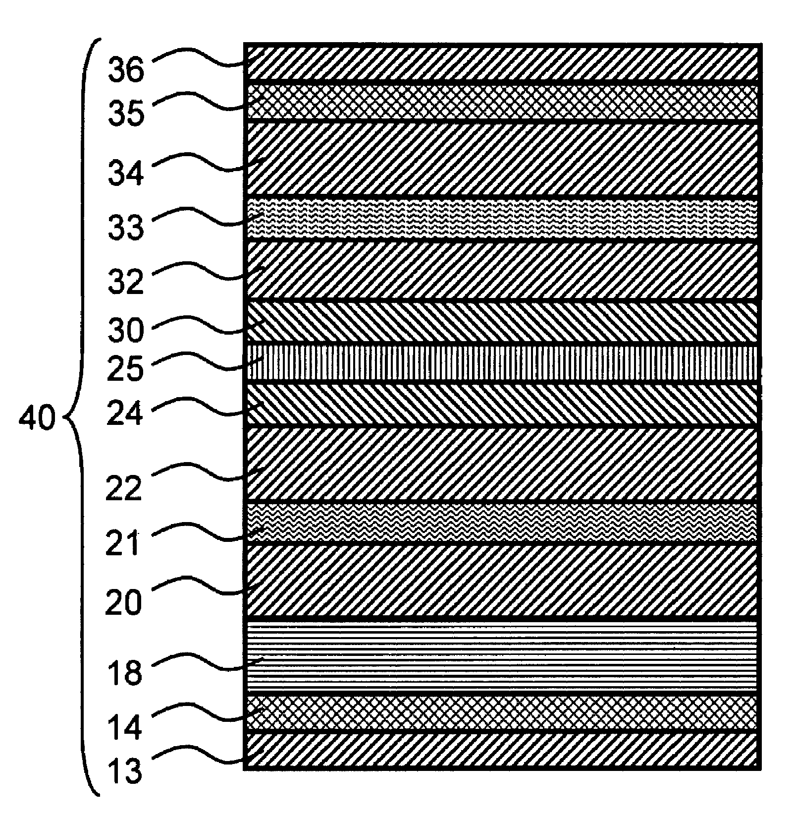
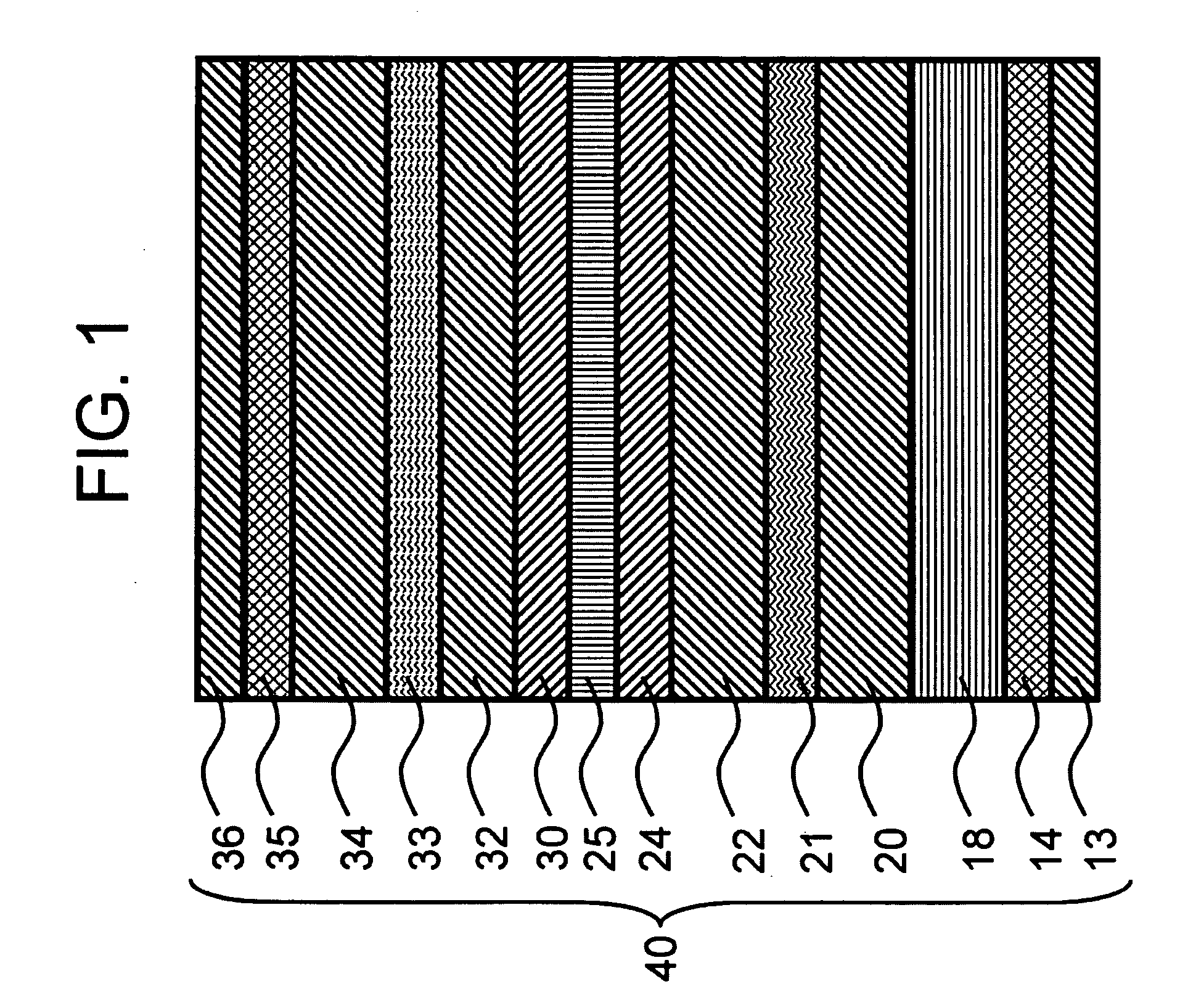
[0100]A tunnel junction device according to Example 1 was produced using the following procedure to determine the MR ratio described later. An electroconductive layer 12 formed of Ta (3 nm) / Cu (30 nm) was formed on a Si substrate 10 with a magnetron sputtering apparatus to determine the MR ratio by a current-in-plane tunneling (CIPT) method described later. As illustrated in FIG. 6, a first underlying layer 13 formed of Ta (3 nm), a second underlying layer 14 formed of Ru (2 nm), a pinning layer 18 formed of Ir21Mn79 (7 nm), a first pinned magnetic layer 20 formed of Co65Fe35 (2 nm), a nonmagnetic coupling layer 21 formed of Ru (0.8 nm), a second pinned magnetic layer 22 formed of Co40Fe40B20 (2 nm), a first diffusion-blocking layer 24 formed of Co50Fe50 (0.5 nm), an insulating layer 25 formed of MgO (1.0 nm), a second diffusion-blocking layer 30 formed of Co50Fe50 (0.6 nm), a first free magnetic layer 32 formed of Co70Fe10B20 (2 nm), a third diffusion-blocking layer 33 formed of Ta...

example 2

[0101]A ferromagnetic tunnel junction device according to Example 2 was produced in the same manner as Example 1, except that Co50Fe50 (0.6 nm) was replaced by Co50Fe50 (0.4 nm) in the second diffusion-blocking layer 30.

example 3

[0102]A ferromagnetic tunnel junction device according to Example 3 was produced in the same manner as Example 1, except that Co50Fe50 (0.6 nm) was replaced by Co50Fe50 (0.2 nm) in the second diffusion-blocking layer 30.


PUM


Abstract

According to an aspect of an embodiment, a ferromagnetic tunnel junction device includes: a first pinned magnetic member including a ferromagnetic material having a boron atom; a second pinned magnetic member including a ferromagnetic material on the first pinned magnetic member, the content of the boron atom in the second pinned member being smaller than that in the first pinned member; and a first free magnetic member superposed with respect to the second pinned layer, including a ferromagnetic material. The ferromagnetic tunnel junction device further includes: an insulating layer between the second pinned magnetic layer and the first free magnetic layer; and a second free magnetic member including a ferromagnetic material having a boron atom on the first free magnetic member, the content of the boron atom in the second free member being smaller than that in the first free member.

Description

CROSS REFERENCE TO RELATED APPLICATIONS[0001]This application is based upon and claims the benefit of priority from the prior Japanese Patent Application No. 2007-328143 filed on Dec. 20, 2007, the entire content of which is incorporated herein by reference.BACKGROUND[0002]1. Technical Field[0003]This art relates to a ferromagnetic tunnel junction, which is a magnetoresistive element having an electrical resistance varying with a magnetic field.[0004]2. Description of the Related Art[0005]Ferromagnetic tunnel junctions have a structure of ferromagnetic metal layer / insulating layer / ferromagnetic metal layer, and the insulating layer has an energy barrier through which electrons can pass by tunnel effect. A slash “ / ”, as used herein, indicates that materials or layers on both sides of the slash are layered. The tunneling probability (tunneling resistance) is known to depend on the magnetization state of the ferromagnetic metal layers on both sides. The tunneling resistance can therefo...

Claims


Application Information

Patent Timeline
IPC IPC(8): G11B5/33
CPCB82Y10/00B82Y25/00G11C11/16G11B5/3909G11B5/3929G01R33/093G11C11/161G11C11/1657G11C11/1659G11C11/1673G11C11/1675
Inventor KAWAI, KENICHINISHIOKA, YASUSHIHAMADA, YUSUKE
Owner FUJITSU LTD
Why Eureka
Try Eureka