Heat dissipating structure

a technology of heat dissipation structure and electronic equipment, which is applied in the direction of electrical equipment casings/cabinets/drawers, insulated conductors, instruments, etc., can solve the problems of affecting reliability and lifetime of electronic equipment, unable to efficiently exhaust heat generated by heat sources, etc., to prevent the increase in the temperature inside the electronic equipment caused by accumulated heat, reduce the size of the housing for assembling the heat dissipation structure, and improve the reliability and lifetime of products

Active Publication Date: 2009-06-25
PEGATRON
View PDF7 Cites 2 Cited by
  • Summary
  • Abstract
  • Description
  • Claims
  • Application Information

AI Technical Summary

Benefits of technology

[0010]As mentioned above, in the heat dissipating structure and electronic apparatus of the invention, the horizontal position of the first heat dissipating element relative to the second heat dissipating element can be adjusted by the elastic element of the position-adjusting unit. In addition, the heat generated by the heat source can be transmitted to the first heat dissipating element through the second heat dissipating element. Since the first and second heat dissipating elements can be relatively moved in horizontal, the additional space for the rotational movement of the heat dissipating elements is not needed. Thus,

Problems solved by technology

However, since the electronic devices in the housing are arranged closely, the heat generated by the heat sources can not be exhausted efficiently.
If

Method used


Image

  • Heat dissipating structure
  • Heat dissipating structure
  • Heat dissipating structure

Examples


Embodiment Construction

[0017]The preferred embodiment of the present invention will be apparent from the following detailed description, which proceeds with reference to the accompanying drawings, wherein the same references relate to the same elements.

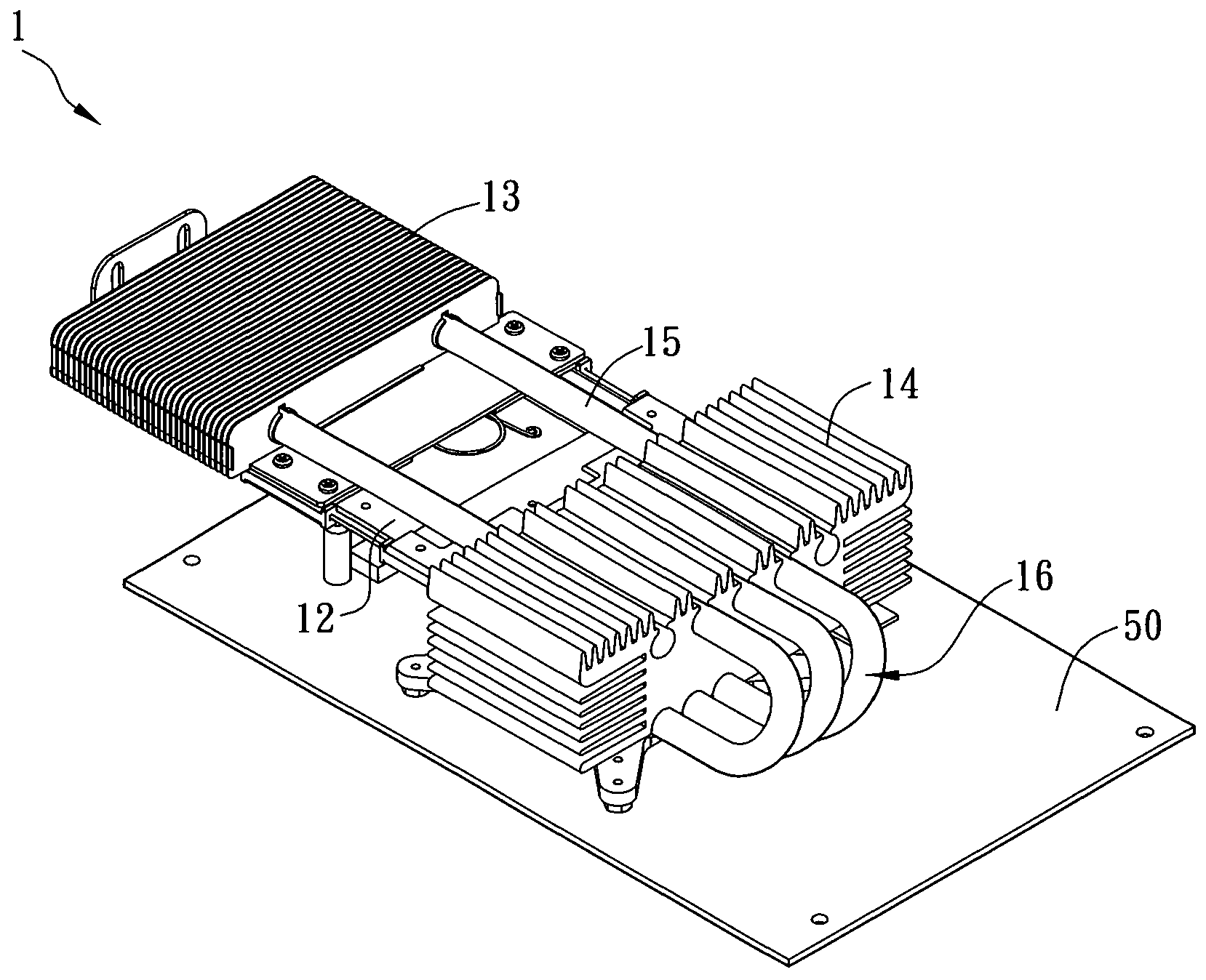
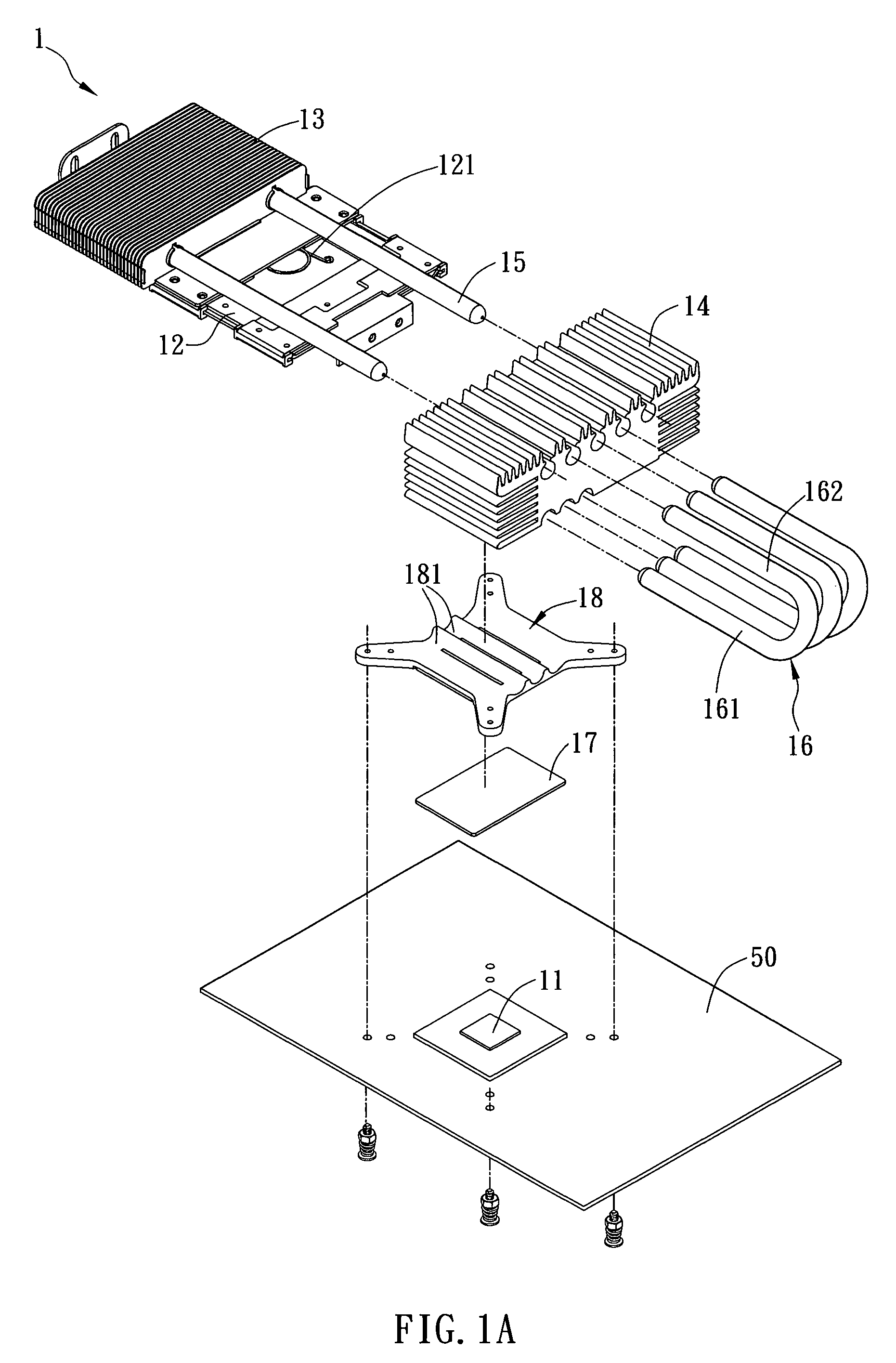
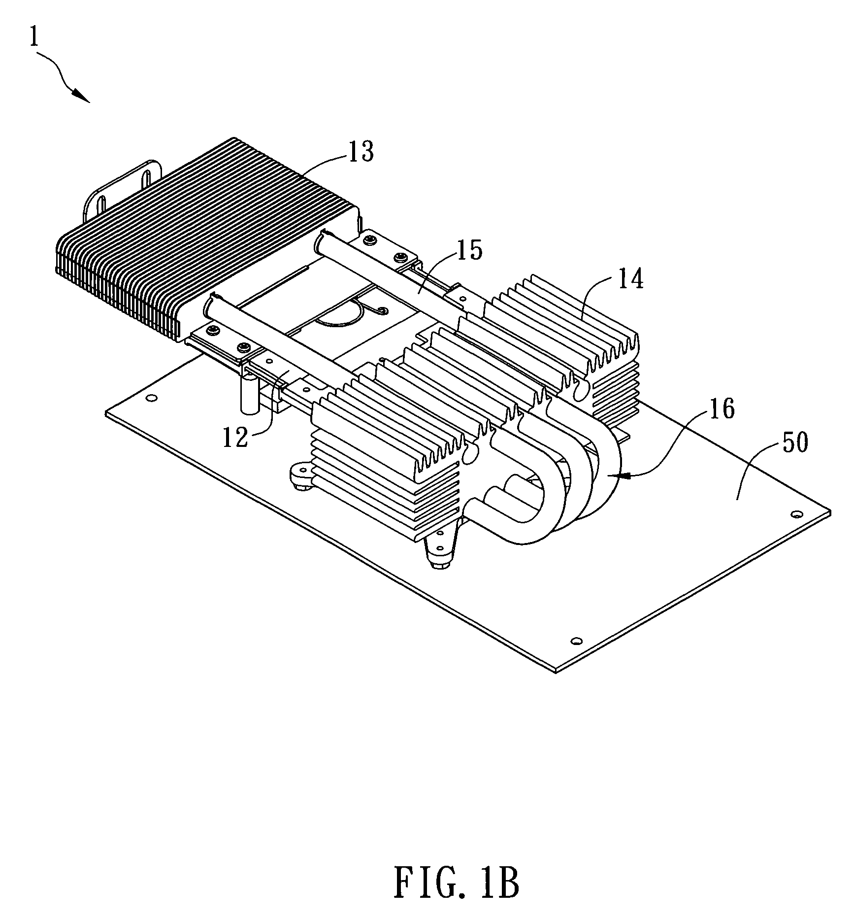
[0018]With reference to FIGS. 1A and 1B, a heat dissipating structure 1 according to a preferred embodiment of the invention is cooperated with a heat source 11. The heat dissipating structure 1 includes a position-adjusting unit 12, a first heat dissipating element 13, a second heat dissipating element 14 and a first heat conducting element 15. In the embodiment, the heat source 11 can be, for example but not limited to, a CPU (central processing unit), a microprocessor, a display chip, a graphic chip, a north-bridge chip, a south-bridge chip or a memory. The heat source 11 can be disposed on a circuit board 50. In the embodiment, the circuit board 50 may be a motherboard or a graphics card.

[0019]The first heat dissipating element 13 is connected with the ...


PUM


Abstract

A heat dissipating structure for a heat source includes a position-adjusting unit, a first heat dissipating element, a second heat dissipating element and a first heat conducting element. The position-adjusting unit has an elastic element. The first heat dissipating element is connected with the position-adjusting unit. The second heat dissipating element contacts with the heat source. One end of the first heat conducting element contacts with the first heat dissipating element, and the other end of the first heat conducting element contacts with the second heat dissipating element. The position-adjusting unit adjusts the position of the first heat dissipating element relative to the second heat dissipating element by the elastic element.

Description

CROSS REFERENCE TO RELATED APPLICATIONS[0001]This Non-provisional application claims priority under 35 U.S.C. §119(a) on Patent Application No(s). 096149424 filed in Taiwan, Republic of China on Dec. 21, 2007, the entire contents of which are hereby incorporated by reference.BACKGROUND OF THE INVENTION[0002]1. Field of Invention[0003]The invention relates to a heat dissipating structure and an electronic apparatus utilizing the heat dissipating structure.[0004]2. Related Art[0005]The function of the microprocessor has been improved, so the processing speed thereof become faster and faster. In addition, the size of the host as well as the sizes of the components in the host is reduced, so that the generated heat is increased. Thus, various kinds of heat dissipating structures are evolved continuously so as to provide better heat dissipating effect.[0006]The conventional heat dissipating structure may be a heat sink disposed on an electronic device. Then, a fan unit is utilized to ind...

Claims


Application Information

Patent Timeline
IPC IPC(8): G06F1/20H05K7/20
CPCG06F1/20
Inventor CHENG, HSUEH-LUNGTSAI, MING-FENG
Owner PEGATRON
Why Eureka
Try Eureka