DC component elimination at output voltage of pwm inverters

a technology of pwm inverters and components, which is applied in the direction of power conversion systems, emergency protective circuit arrangements, electrical equipment, etc., can solve the problems of high transformers of this type, particularly problematic for power systems in vehicles, and adverse effects on ac loads

Inactive Publication Date: 2009-06-25
HONEYWELL INT INC
View PDF25 Cites 30 Cited by
  • Summary
  • Abstract
  • Description
  • Claims
  • Application Information

AI Technical Summary

Problems solved by technology

Presence of an excessive DC component in the output may have an adverse effect on AC loads that may be driven by the output.
This may be particularly problematic for power systems in a vehicle such as an aircraft or aerospace vehicle.
Transformers of this type are expensive.
In a power system of an aerospace vehicle, transformers may also add undesirable weight.
In the context of such a measurement system, it is difficult to provide an accurate quantification of the DC component.
Such rigorous requirements demand measurement and compensation accuracy that is not available from prior art systems.
If, for example, quantification of the DC component must be made to an accuracy of + / −0.1V, then it is exceedingly difficult to achieve the requisite accuracy when the overall DC component represents only a small fraction of the measured voltage, i.e. 115 Vrms.

Method used


Image

  • DC component elimination at output voltage of pwm inverters
  • DC component elimination at output voltage of pwm inverters
  • DC component elimination at output voltage of pwm inverters

Examples


Embodiment Construction

[0018]The following detailed description is of the best currently contemplated modes of carrying out the invention. The description is not to be taken in a limiting sense, but is made merely for the purpose of illustrating the general principles of the invention, since the scope of the invention is best defined by the appended claims.

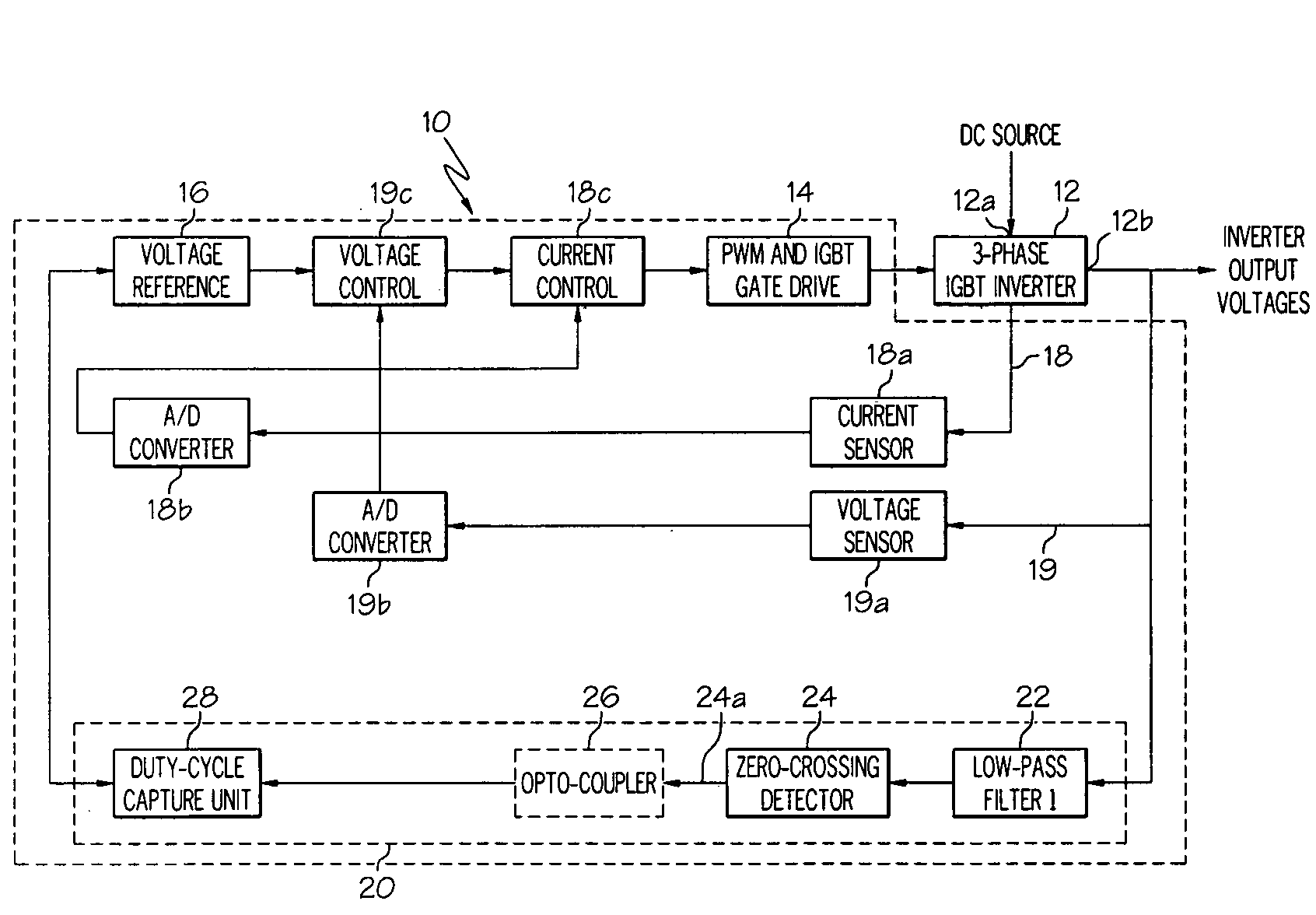
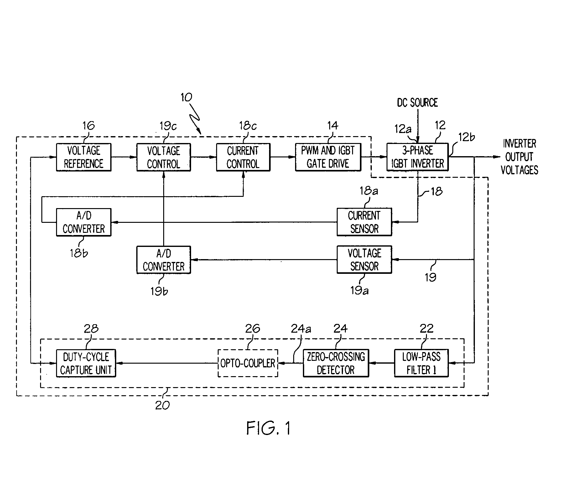
[0019]Broadly, the present invention may be useful in controlling an output of a PWM inverter in a power distribution system. More particularly, the present invention may reduce harmful effects of a DC component of the output of the inverter. The present invention may be particularly useful in vehicles such as aircraft which require rigorous and precise control of the DC component. Aerospace vehicles also require that their power distribution systems are constructed with a reduced number of expensive and heavy elements such as transformers.

[0020]In contrast to prior-art PWM inverter-based power distribution control systems, which employ DC component iso...


PUM


Abstract

A control system for a PWM inverter may reduce a DC component of an output of the inverter. An output voltage signal may be attenuated with a low-pass filter to produce a signal with a high DC content. A duty cycle of an output of the low pass filter may be determined with a zero-crossing detector. A calculation may be performed to determine a magnitude of a DC offsetting voltage that may offset the DC component of the inverter output. The inverter may be commanded to produce a DC offsetting voltage with an opposite polarity from the DC component of the inverter output. The opposite polarity DC offsetting voltage may effectively cancel the DC component of the inverter output. A monitoring system may employ an alternate system for determining the level of the DC component, thus providing a desirable redundancy to the system.

Description

BACKGROUND OF THE INVENTION[0001]The present invention is in the field of electrical power systems and, more particularly, those power systems which produce direct current (DC) that is converted to alternating current (AC).[0002]Many electrical power systems use a DC power source to supply electrical power to AC loads. An inverter operating with a pulse width modulation (PWM) system is commonly used to convert the DC power to AC power. PWM inverters may be designed to produce three phase power outputs at a desired AC frequency such as 400 hertz (Hz.). But, as is well known, three phase PWM inverters inherently deliver an output that includes a DC component. Presence of an excessive DC component in the output may have an adverse effect on AC loads that may be driven by the output. This may be particularly problematic for power systems in a vehicle such as an aircraft or aerospace vehicle. Consequently, electrical distribution systems that utilize AC power from a PWM inverter are ofte...

Claims


Application Information

Patent Timeline
Patent Type & Authority Applications(United States)
IPC IPC(8): H02M7/537
CPCH02M2007/4803H02M7/5387H02M7/4803
Inventor ZHANG, HONGENG, JEREMY
Owner HONEYWELL INT INC
Why Eureka
Try Eureka