Method and Apparatus for Variable Frame Rate

Inactive Publication Date: 2009-06-25
TEXAS INSTR INC
View PDF4 Cites 13 Cited by
  • Summary
  • Abstract
  • Description
  • Claims
  • Application Information

AI Technical Summary

Benefits of technology

[0009]Therefore, there is a need for an improved method and/or appa

Problems solved by technology

In some cases, these frequencies may not satisfy the need for displaying the video content seamlessly, due

Method used


Image

  • Method and Apparatus for Variable Frame Rate
  • Method and Apparatus for Variable Frame Rate
  • Method and Apparatus for Variable Frame Rate

Examples


Embodiment Construction

[0018]For the purposes of this application, a computer readable medium is any medium accessible by a computer for reading, writing, executing, and the like of data and / or instructions.

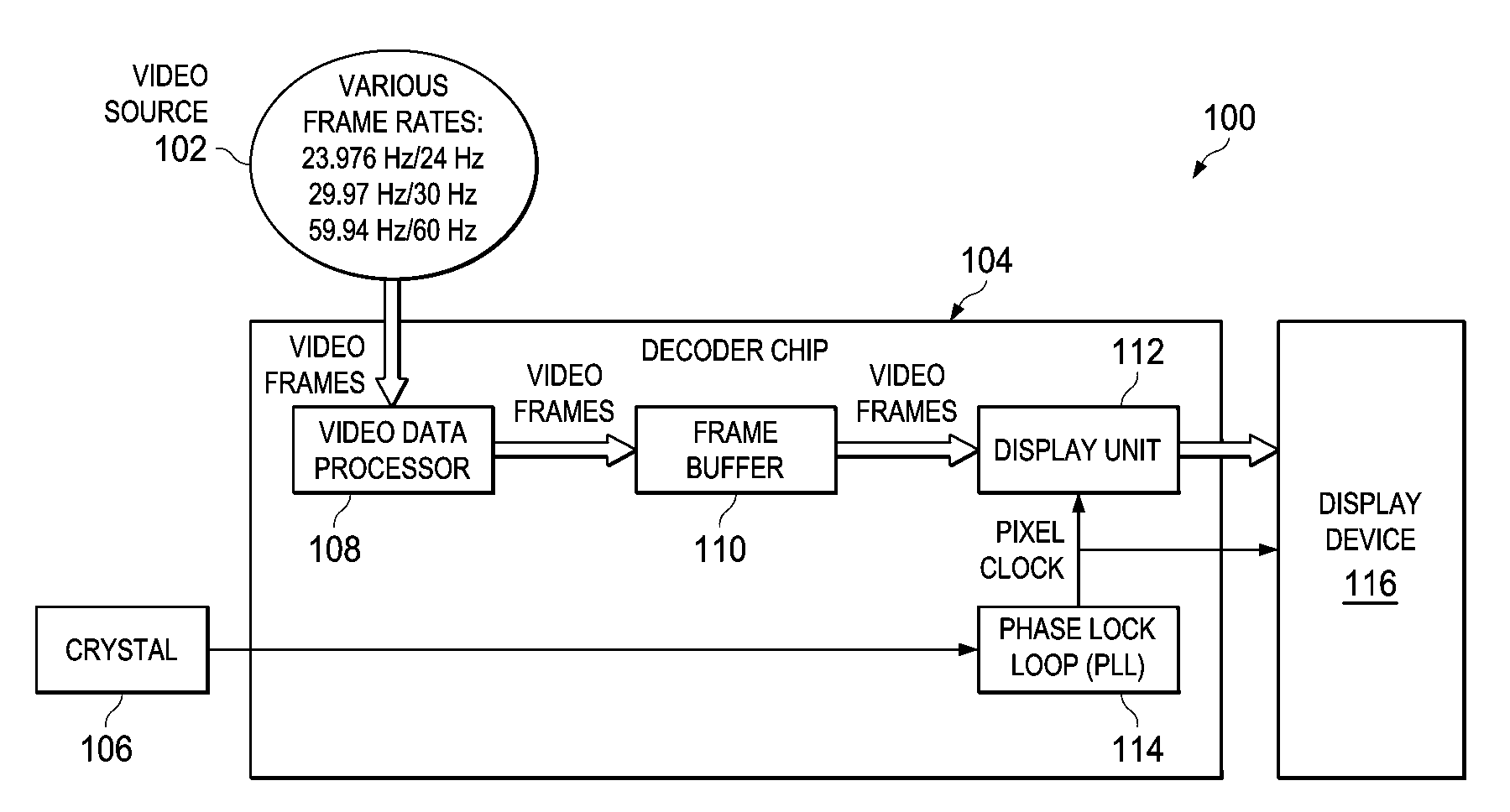
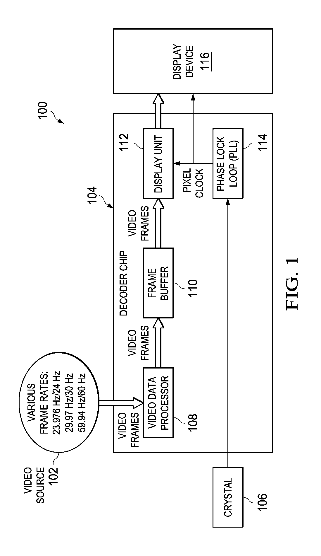
[0019]FIG. 1 is an embodiment of a digital video system 100. More specifically, FIG. 1 is a simplified HDTV video display system. FIG. 1 includes a video source 102, a decoder chip 104, a crystal 106 and a display device 116. The decoder chip 104 includes a video processor 108, a frame buffer 110, a display unit 112 and a phase-locked loop (PLL) 114. The PLL used in the system is Flying-Adder phase-locked PLL. The equation of Flying-Adder Flying-Adder phase-locked PLL can be expressed as:

Ts=1 / fs=FREQ*Δ  (1)

Where Ts, or fs, is the synthesizer's output period or frequency. FREQ is the digital control word. A is the time difference between any two adjacent VCO outputs.

[0020]Starting from video source 102, video frames sequentially pass through at least one video data processor 108 inside the decoder chip ...


PUM


Abstract

A method and apparatus for adjusting to a frame rate. The method displays the video frames with varying rates. The method comprising the steps of detecting a change in the frame rate, calculating the FREQ of the frame, adjusting the phase-locked loop utilizing the calculated FREQ, and utilizing the adjusted phase-locked loop output as the pixel clock to display the frame.

Description

CROSS-REFERENCE TO RELATED APPLICATIONS[0001]This application claims benefit of U.S. provisional patent application Ser. No. 61 / 015,438, filed Dec. 20, 2007, which is herein incorporated by reference.BACKGROUND OF THE INVENTION[0002]1. Field of the Invention[0003]Embodiments of the present invention generally relate to a method and apparatus for efficiently dealing with variable rate among frames.[0004]2. Description of the Related Art[0005]In digital TV broadcasting, the frame rate of the video signal is not constant; rather it varies dependent on the factors, such as, video source. Different video contents are derived from different video sources that bear their own frame rates. For example, when a movie is broadcasted in 720p, it could use 59.94 Hz frame rate. However, during the commercial breaks, the frame rate used for advertisement program might be in 60 Hz. Consequently, in digital TV receiving system, the hardware must be designed to handle this frame rate difference. Hence...

Claims


Application Information

Patent Timeline
IPC IPC(8): H03D3/24
CPCG09G5/008G09G2340/0435H03L7/18H04N21/440281H04N7/0122H04N21/4305H04N5/46
Inventor XIU, LIMINGLIAN, HONGBINGCOOK, GRADYTRACY, CHRISTOPHER SEANLI, WEN
Owner TEXAS INSTR INC
Why Eureka
Try Eureka