
Image coding/decoding method, image coding apparatus and image decoding apparatus

a coding apparatus and image technology, applied in image enhancement, image analysis, instruments, etc., can solve the problems of coding distortion remarkably on the boundary of the block, the inability to reconstruct the base which is important for representing image signals, and the worsening of the reproducibility of coefficients, etc., to achieve small distortion

Inactive Publication Date: 2009-06-25
NTT DOCOMO INC
View PDF21 Cites 6 Cited by
  • Summary
  • Abstract
  • Description
  • Claims
  • Application Information

AI Technical Summary

Benefits of technology

[0011]A first object of the present invention is to provide an image coding / decoding method in which an decoded image having small distortion can be obtained even when the standard coding / decoding method using DCT is applied.

Problems solved by technology

On the other hand, when coding an image at a very low bit rate, quantization becomes rough so that reproducibility of coefficients becomes worse.
Thus, a problem occurs in that the base which is important for representing image signal can not be reconstructed.
In addition, DCT performs processing on the region closed in the 8×8 pixel blocks, distortion of coding tends to appear remarkably on boundaries of the block.
Due to this tendency, block distortion occurs so that components which are not visually included in the signal appears on the image.
Thus, it is detected as noise which is very conspicuous.
Thus, high frequency coefficients important for reproducing the edge are lost.
Due to such processing, conspicuous noise which is intrinsic to DCT appears in the edge part so that image degradation occurs.
However, according to the conventional image coding apparatus, the standard coding method using the existing DCT as-is can not be applied.

Method used


Image

  • Image coding/decoding method, image coding apparatus and image decoding apparatus
  • Image coding/decoding method, image coding apparatus and image decoding apparatus
  • Image coding/decoding method, image coding apparatus and image decoding apparatus

Examples


Embodiment Construction

[0126]In the following, embodiments of the present invention will be described with reference to figures.

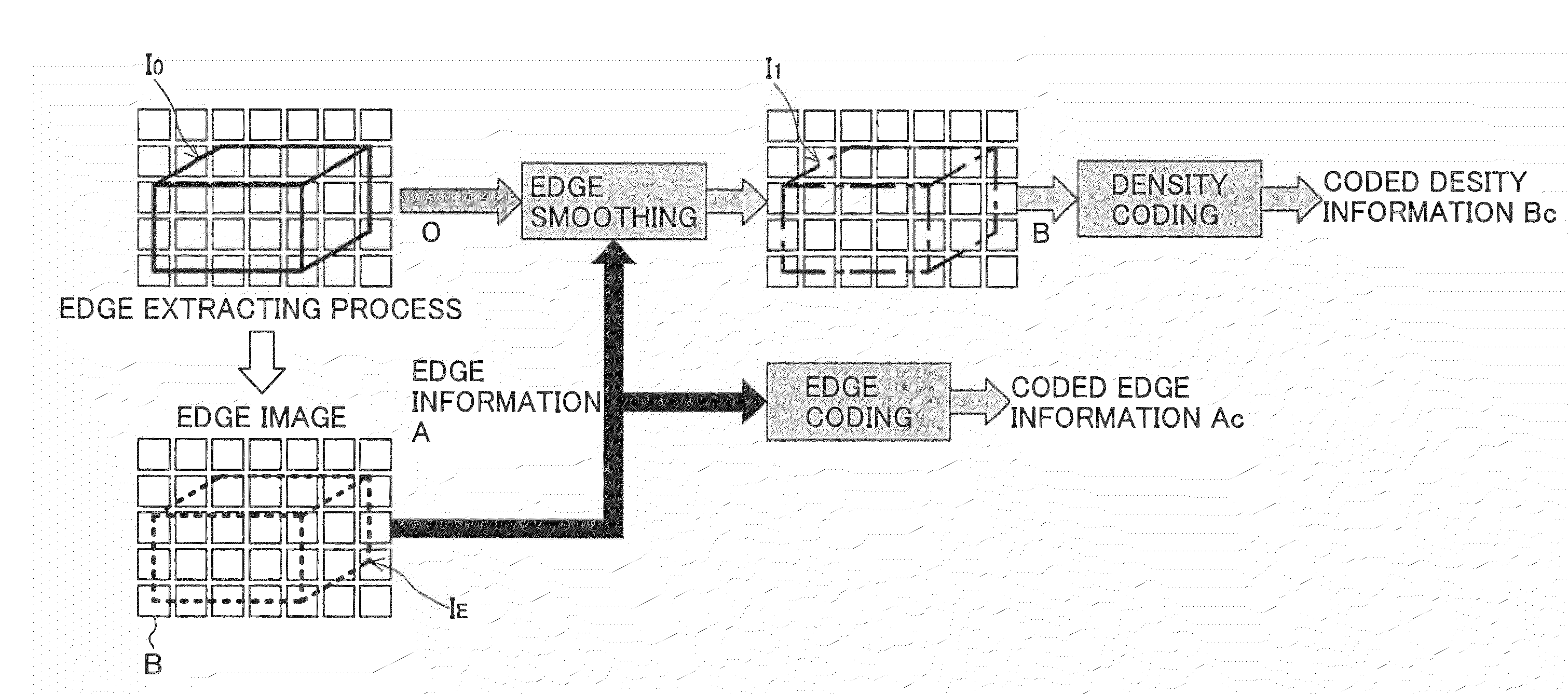
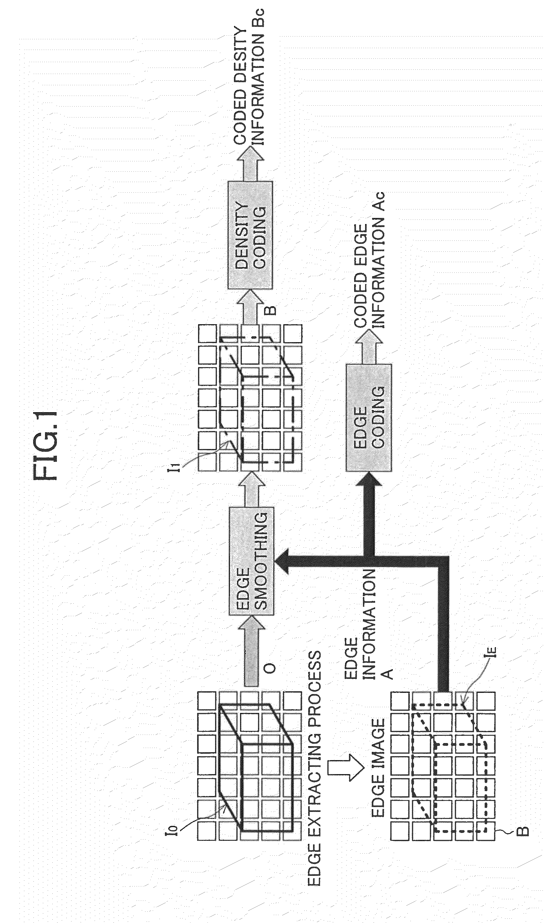
[0127]The principle of processes performed by an image coding apparatus of an embodiment of the present invention is as shown in FIG. 1 for example.

[0128]As shown FIG. 1, edge information A is extracted from an original image IO which is represented by density information O (for example, luminance level) for each pixel, in which the edge information A represents the edge part IE of the original image IC. The extracted edge information A is coded according to a standard coding algorithm such as JBIG and the like so that coded edge information AC is obtained. From the extracted edge information A, processes for smoothing the edge part IE are performed on the density information representing the original image IO so that density information B of an edge smoothed image I1 is obtained for each pixel. The density information B of the edge smoothed image I1 is coded according to the sta...


PUM


Abstract

An image coding method is provided, in which the method includes the steps of: extracting edge information which represents an edge part of an original image; obtaining density information of an edge smoothed image from the original image by smoothing the edge part; obtaining coded edge information by coding the edge information according to a first coding algorithm; obtaining coded density information by coding the density information of the edge smoothed image according to a second coding algorithm; and sending the coded edge information and the coded density information as coded information to an image decoding apparatus.

Description

CROSS REFERENCE[0001]This application is a continuation of and is based upon and claims the benefit of priority under 35 U.S.C. § 120 for U.S. Ser. No. 10 / 003,113, filed Dec. 6, 2001, the entire contents of each which are incorporated herein by reference. U.S. Ser. No. 10 / 003,113 claims the benefit of priority under 35 U.S.C. § 119 from Japanese Patent Application Nos. 2001-072904, filed Mar. 14, 2001 and 2000-373462, filed Dec. 7, 2000.BACKGROUND OF THE INVENTION[0002]1. Field of the Invention[0003]The present invention relates to an image coding / decoding method used for coding original images such as a moving image and a still image, and decoding coded images. More particularly, the present invention relates to an image coding / decoding method which can decrease noise for decoding coded images while applying a standardized algorithm such as MPEG-1 / 2 / 4 and the like.[0004]In addition, the present invention relates to an image coding apparatus and an image decoding apparatus which per...

Claims


Application Information

Patent Timeline
Patent Type & Authority Applications(United States)
IPC IPC(8): G06K9/36G06K9/48G06T5/00G06T5/20G06T9/00G06T9/20H03M7/30H04N1/407H04N1/409H04N1/41H04N19/463H04N19/60H04N19/625H04N19/70H04N19/80H04N19/85H04N19/86H04N19/90
CPCG06T7/0083G06T2207/10016G06T2207/20052G06T9/20H04N19/44H04N19/80H04N19/61G06T7/12
Inventor SEKIGUCHI, SHUNICHIETOH, MINORU
Owner NTT DOCOMO INC
Learn More