Network system and optical line terminal

a network system and optical line terminal technology, applied in the field of network system and optical line terminal, can solve the problems of increasing the cost of transmission devices, accelerating infrastructure-providing businesses, and exposing price competition, so as to maximize the utilization of existing optical fiber resources and remove signal overlapping

Inactive Publication Date: 2009-06-25
HITACHI LTD
View PDF5 Cites 72 Cited by
  • Summary
  • Abstract
  • Description
  • Claims
  • Application Information

AI Technical Summary

Benefits of technology

[0016]The present invention enables plural PON systems to coexist in order to maximally utilize existing optical fiber resources in optical access system businesses. Specifically, the present invention may provide a communication technology that enables compatibility to new systems and enables various PON systems having different methods to coexist.
[0017]More specifically, the present invention may completely remove signal overlapping between PONs due to being capable of sharing or intensively managing bandwidth use conditions over an optical fiber that serves as a common bandwidth between plural systems by synchronizing transmission clocks between plural systems.

Problems solved by technology

Costs required to replace transmission devices become significantly problematic as FTTH services are being prevalently used.
Due to the increase of the speed of DSL and the DSL speed is migrating toward using FTTH, which in turn accelerates infrastructure-providing businesses and exposes price competition.
Therefore, cost has recently become an important issue in optical access systems and the main topic in respects to standardization.
In a case where plural systems coexist, it is problematic how to remove interference between the systems.

Method used


Image

  • Network system and optical line terminal
  • Network system and optical line terminal
  • Network system and optical line terminal

Examples


Embodiment Construction

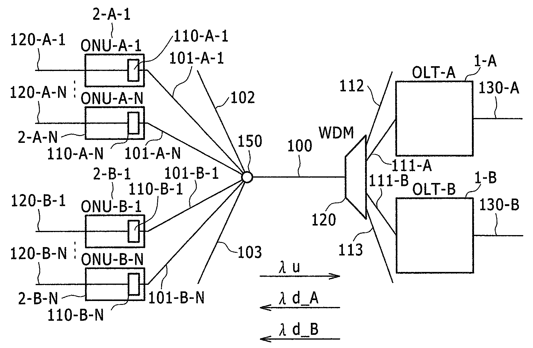
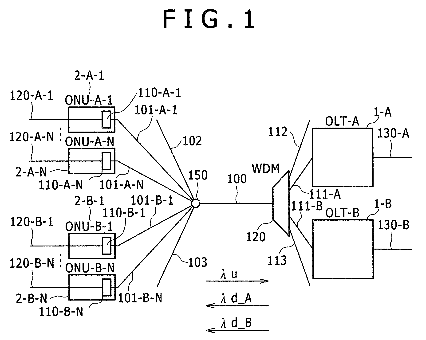
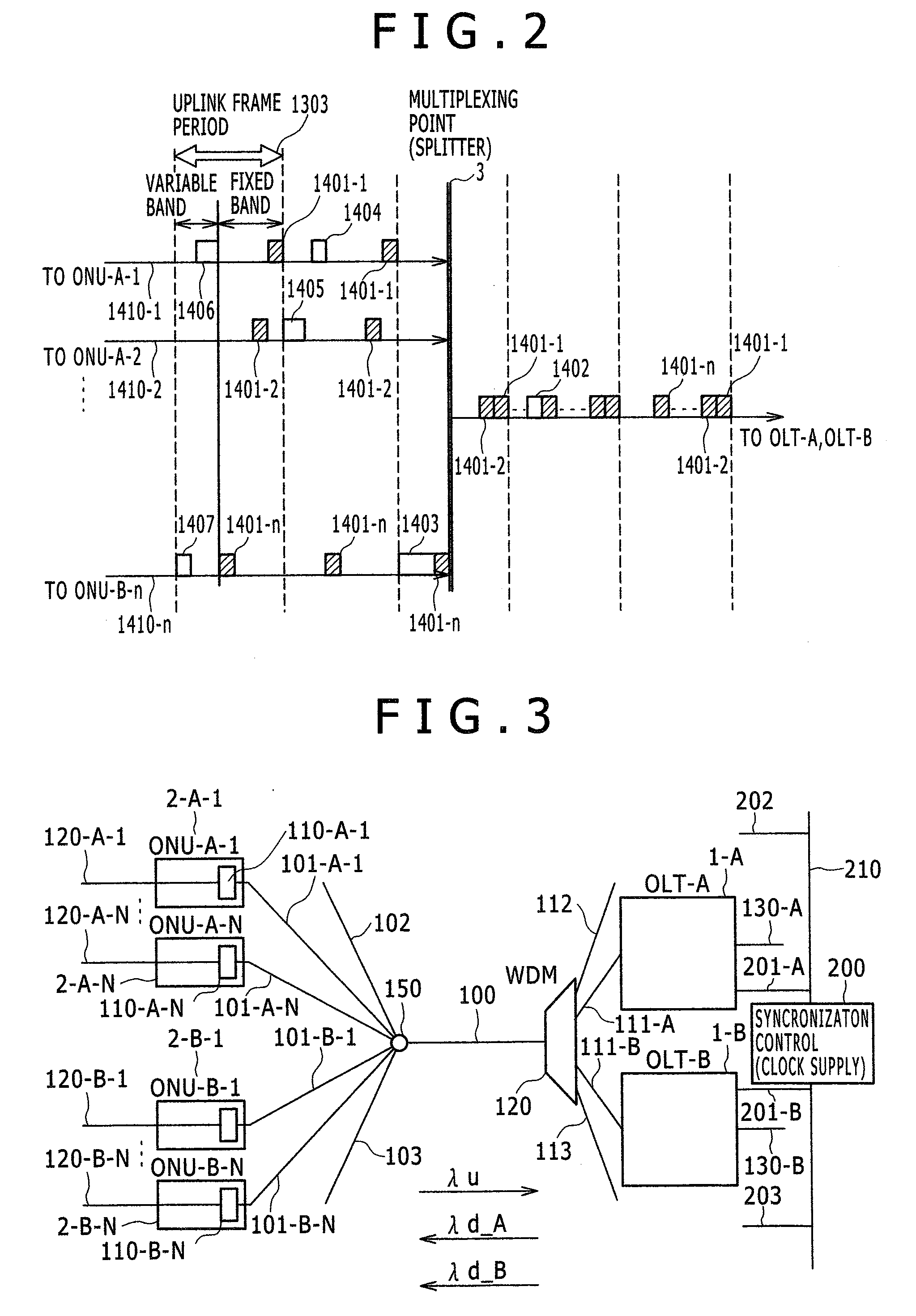
[0078]The object of the present invention aims to minimally suppress an influence on the other systems and an influence on data for communication, which take place when an optical fiber is shared by plural PON systems and is caused by a ranging process in a certain system. Therefore, a mechanism has been achieved in which PON section communication timing of each system is shared between PON systems that share an optical fiber. This enables efficient operation of the plural PONs while maintaining basic functions of PON. Plural variations may be considered in the mode of disposing the PONs but the present invention may apply to all of the configurations. Plural variations are considered when plural PONs are disposed in the form of sharing an optical fiber. An example includes a case where the plural PONs use a common upstream wavelength or a common downstream wavelength. For a system configured in such an organization, four methods are generally considered according to combinations of...


PUM


Abstract

It is necessary to completely remove overlapping of signals between plural PONs in order to make the PONs coexist. Accordingly, it is required to share or intensively manage bandwidth use conditions over an optical fiber that serves as a common band between plural systems. Therefore, transmission clocks should be synchronized with high accuracy between plural systems. A reference clock is provided from an external device or a representative OLT to the entire systems to perform clock synchronization between plural systems, so that the overall systems are synchronized by synchronizing each OLT with the reference clock. A hierarchical management method is selected that manages ONUs under the control of each OLT by managing band use information arranged for each OLT with respect to an external device or a representative OLT for sharing of bandwidth use conditions between plural systems.

Description

CLAIM OF PRIORITY[0001]The present application claims priority from Japanese patent application JP2007-329498 filed on Dec. 21, 2007, the content of which is hereby incorporated by reference into this application.BACKGROUND OF THE INVENTION[0002]1. Field of the Invention[0003]The present invention relates to a system control method that enables managing of ONUs, securing of communication bands, and identifying of communication data in each of plural systems that are disposed to share an optical fiber when plural optical access devices are installed.[0004]2. Description of the Related Art[0005]Due to the increased demands for broad bands, phone line-based access technologies such as Digital Subscriber Line (DSL) and the like are replaced by large-capacity access lines using optical fibers as user-dedicated access lines. Optical access line type is generally classified into two types. One type is called “media converter (MC)” and this is a method of connecting optical fibers from a st...

Claims


Application Information

Patent Timeline
Patent Type & Authority Applications(United States)
IPC IPC(8): H04J14/00
CPCH04J3/0655H04J3/0682H04Q2011/0079H04Q11/0067H04Q2011/0064H04L7/0008
Inventor MIZUTANI, MASAHIKOSUGAWARA, TOSHIKIIKEDA, HIROKI
Owner HITACHI LTD
Why Eureka
Try Eureka