
Hand Held Portable Drill Leverage Unit

Inactive Publication Date: 2009-06-25
GLODOWSKI MICHAEL MR
View PDF43 Cites 13 Cited by
  • Summary
  • Abstract
  • Description
  • Claims
  • Application Information

AI Technical Summary

Benefits of technology

[0017]The present invention is a device that not only allows the user to provide leveraged power to the workpiece, but also mitigates or absorbs torque forces experienced by the drill. The present device is relatively simple to manufacture, transport to a job site, for example, and use repeatedly. Further, the present apparatus allows relatively quick mounting thereof to an existing workbench or other substantially fixed support base, and is easily reversible to allow the drill to operate in either of two opposing directions as desired. The present apparatus is also relatively easy to mount to an existing power drill, and is easily adjusted to initially bring the drill into close proximity to the workpiece. Other features and advantages of the present invention will become apparent from the following more detailed description, taken in conjunction with the accompanying drawings, which illustrate, by way of example, the principles of the invention.

Problems solved by technology

When torque of the drill is experienced, if the operator does not adequately resist such torque forces the hole will not be drilled to the proper size since the drill bit angle may change, rendering the hole oblong instead of circular.
Further, such torque forces can cause the drill to slip out of the operator's hand, or jerk the operator's hand dangerously if the drill bit “grabs” the workpiece.
Further, depending on the material being cut and the sharpness of the drill bit, the operator may have to exert significant force against the drill and workpiece, which over time can cause operator fatigue.
If there are a relatively large number of holes to be drilled in the workpiece, the operator may become fatigued before all of the intended holes are drilled.
However, such devices do not provide means for mitigating or absorbing torque forces against the drill, and thus the operator must still provide some torque stabilizing effort when using such devices.
Further, several of these prior art devices require a separate backstop or support surface which might not always be conveniently available, thereby rendering such devices useless.
However, such devices must also have a backstop surface to press against, which might not always be at hand.
However, such a device requires a relatively large carriage assembly and vertical column, and a relatively complex gearing arrangement, resulting in a heavy tool that is difficult to transport and use.
Further, such a device is relatively expensive due to the number of components.
However, such a device also requires a backing surface to be used, and positions an actuator lever in an awkward location behind the drill.
However, such a device includes a relatively complicated mechanism for maintaining a carriage on a bar body.
Due to such complexity, such a device is relatively expensive, relatively difficult to manufacture and use, and is prone to failure due to its relatively large number of moving parts.
Further, such a device may not be easily installed on a stationary support, as can sometimes be desired, particularly when drilling a large number of holes or workpieces.

Method used


Image

  • Hand Held Portable Drill Leverage Unit
  • Hand Held Portable Drill Leverage Unit
  • Hand Held Portable Drill Leverage Unit

Examples


Embodiment Construction

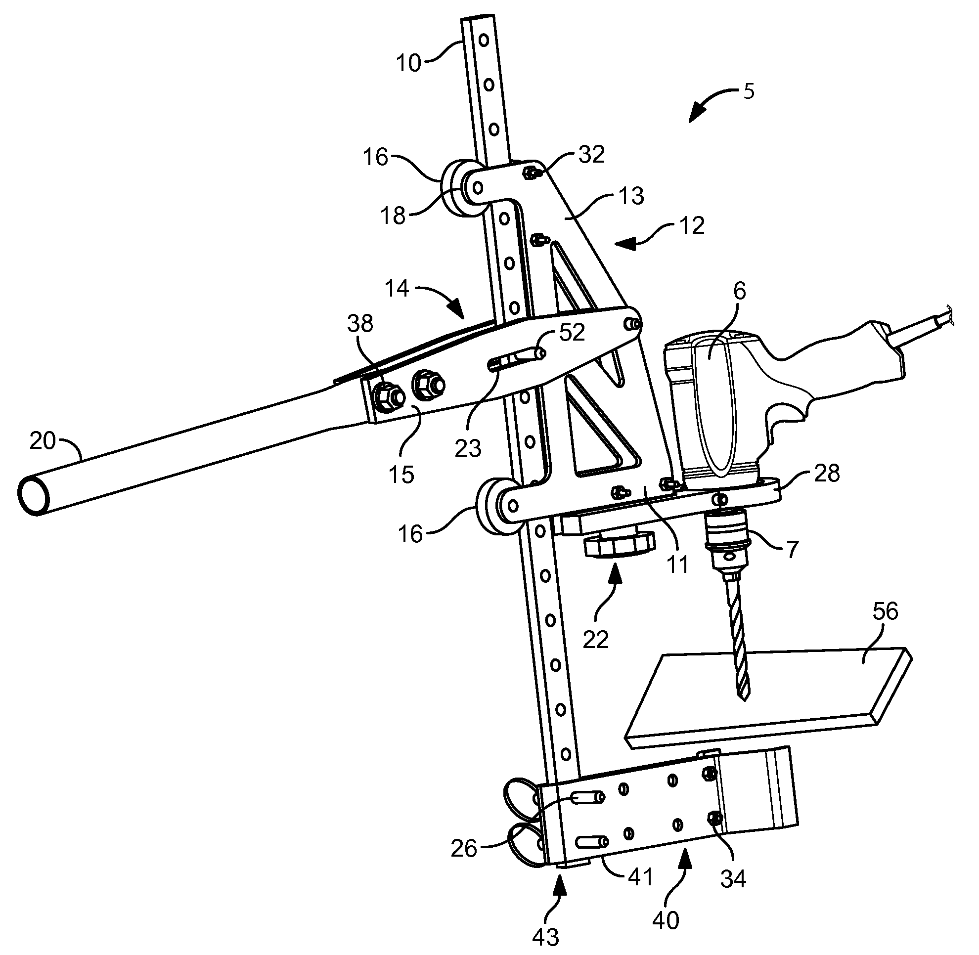
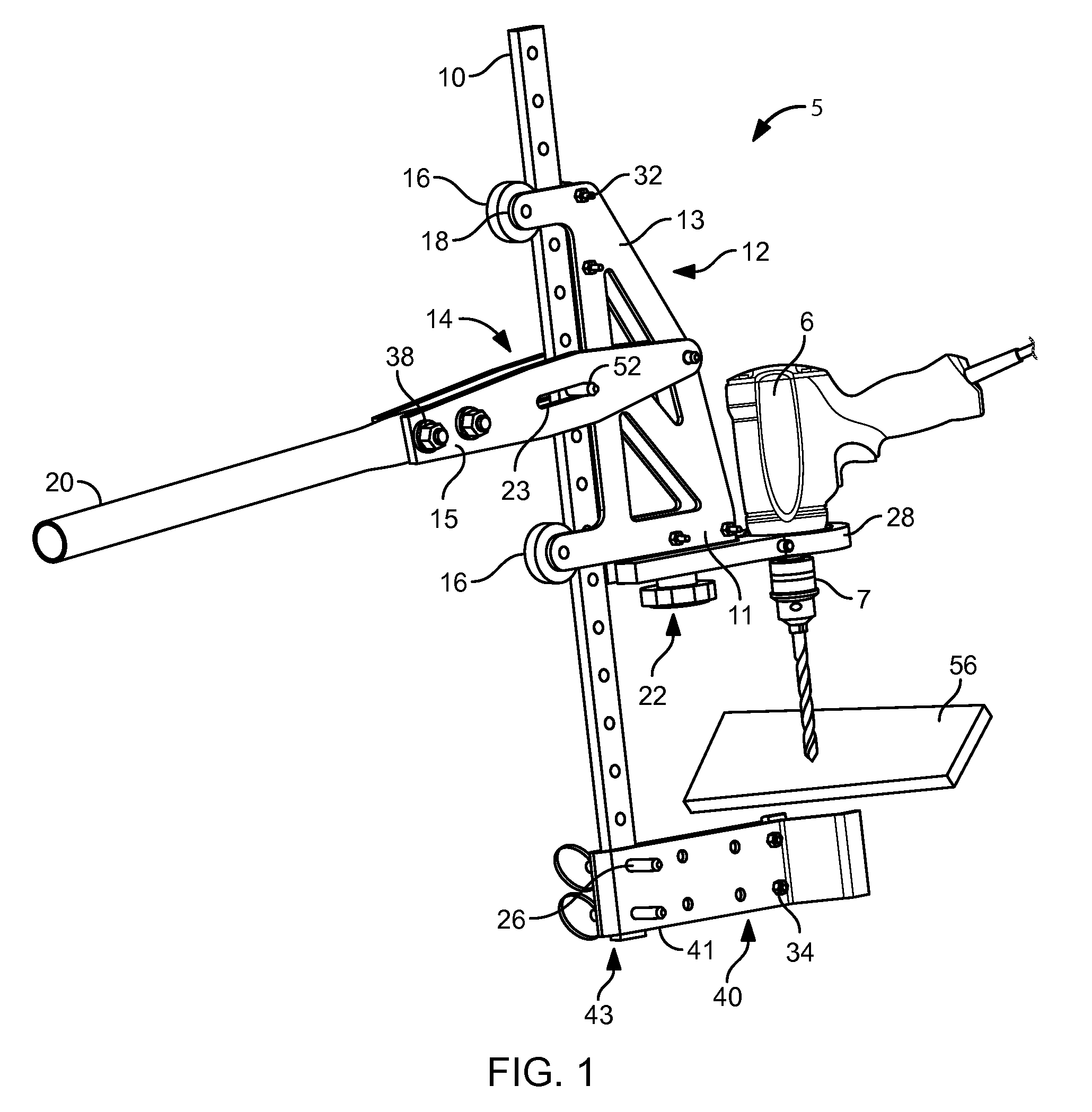
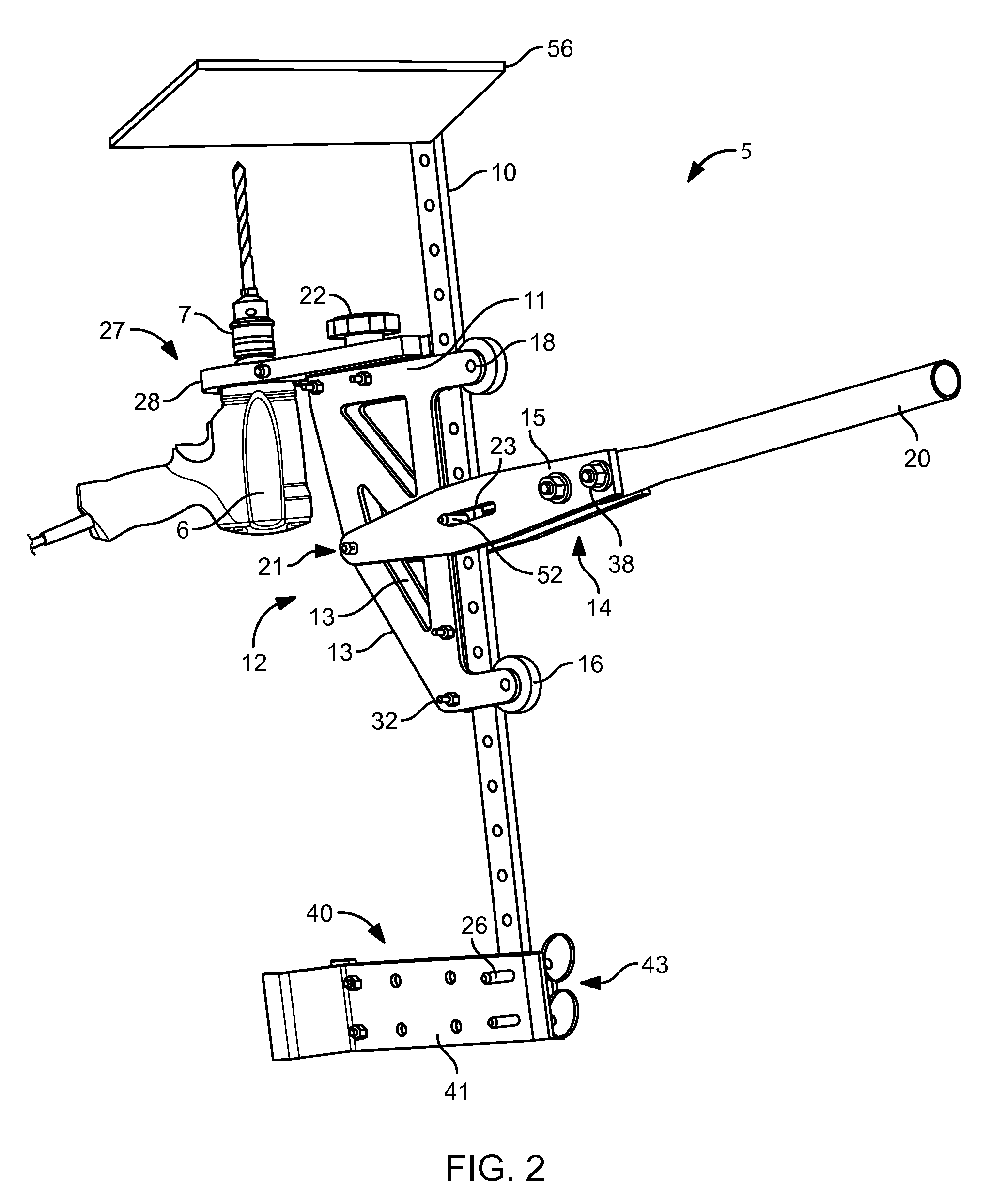
[0026]FIGS. 1 and 3 illustrate a leveraging apparatus 5 for a drill 6 for drilling a workpiece 56. The apparatus 5 includes an elongated, rigid bar body 10 that preferably has at least a proximal side 120, a distal side 130, and two lateral sides 140. The lateral sides 140 both preferably have a plurality of attachment apertures 150 therethrough. Alternately, the bar body 10 may have notches or other suitable attachment means (not shown). The attachment apertures 150 or other attachment means are preferably evenly spaced along the bar body 10. The bar body 10 may be made from any rigid metal stock material, or any suitably durable and rigid plastic or epoxy resin material.

[0027]A carriage 12 is adapted to slidably receive the bar body 10 proximate a rear side 100 thereof. Preferably the carriage 12 is adapted to slidably receive the bar body 10 between at least two rollers 16 each rotationally fixed proximate the rear side 100 of the carriage 12 with a roller pin 18. Alternately, th...


PUM

PropertyMeasurementUnit
Angleaaaaaaaaaa

Abstract

A leveraging apparatus for a drill is disclosed for drilling a workpiece. The apparatus includes a bar body that preferably has a plurality of attachment means there along. A carriage is adapted to slidably receive the bar body and further includes a forward side, and a lower side for mounting with a drill clamping means. An elongated handle is pivotally connected at a distal end thereof proximate the forward side of the carriage. The handle is pivotally, and preferably selectively, attached to the bar body. The clamping means may include a bracket having an aperture therein for selectively receiving the drill therein. A foot means extending away from the bar body is fixed thereto with a bar body attachment means. The foot means is used to brace the workpiece while the handle is used to move the carriage with respect to the bar body to drill the workpiece.

Description

CROSS-REFERENCE TO RELATED APPLICATIONS[0001]This application claims the benefit of U.S. Provisional Patent Application 60 / 962,001, filed on Jul. 24, 2008, and incorporated herein by reference.STATEMENT REGARDING FEDERALLY SPONSORED RESEARCH AND DEVELOPMENT[0002]Not Applicable.FIELD OF THE INVENTION[0003]This invention relates to tools, and more particularly to a tool for drilling.DISCUSSION OF RELATED ART[0004]When using a typical power drill to drill holes in a workpiece, an operator must not only apply pressure against the workpiece to force the rotating drill bit into the workpiece, but he must also maintain a consistent angle of the drill so that the resulting hole is the proper size and shape. When torque of the drill is experienced, if the operator does not adequately resist such torque forces the hole will not be drilled to the proper size since the drill bit angle may change, rendering the hole oblong instead of circular. Further, such torque forces can cause the drill to s...

Claims


Application Information

Patent Timeline
IPC IPC(8): B23B47/00
CPCB25H1/0021Y10T408/6786B25H1/0057
Inventor GLODOWSKI, MICHAELHATTEN, STEVE A.ALLEN, CALVINKEMS, NATHAN
Owner GLODOWSKI MICHAEL MR
Learn More