

Gum Structure Mixing Systems And Methods
a technology of gum structure and mixing system, which is applied in the direction of gum, dough mixing/kneading machine, baking, etc., can solve the problems of single mixer posing significant temperature management difficulties, inherently limited single mixer, etc., and achieves more practical and efficient way of gum formation, convenient or efficient, and convenient.
- Summary
- Abstract
- Description
- Claims
- Application Information
AI Technical Summary
Benefits of technology
Problems solved by technology
Method used
Image

Examples
specific example 1
[0327]A first contemplated example that will be described will focus on the formation of the finished gum structure of Example 7 of Table 3 using mixing system 300 of FIG. 3 and Process 16 of Table 4.
[0328]In this example, mixer 1 takes the form of a continuous mixer 302 in the form of an extruder having a high shear section with high shear extruder elements suitable for dispersive mixing followed by a low shear section with lower shear elements suitable for distributive mixing. The high shear elements may be generally provided between feed ports 321 and 323 while the lower shear mixing elements may be provided between feed ports 324 and 326. While not illustrated, in this example, the high shear section and low shear section can be separated by a chiller portion, such as between feed port 323 and feed port 324.
[0329]In mixer 1 (continuous mixer 302), a first set of gum base ingredients GBIx are added. The finished gum base (FGB) of the desired finished gum (FG) is approximately 25%...
specific example 2
[0337]A second contemplated example that will be described will focus on the formation of the finished gum structure of Example 10 of Table 3 using the mixing system of FIG. 5 and Process 26 of Table 4. In this example, mixer 1 takes the form of continuous mixer 502 in the form of an extruder having a high shear section with high shear extruder elements suitable for dispersive mixing followed by a low shear section with lower shear elements suitable for distributive mixing. The high shear elements may be generally provided between feed ports 521 and 523. The lower shear mixing elements may be provided between feed ports 524 and 526. While not illustrated, in this example, the high shear section and low shear section can be separated by a chiller portion, such as between feed port 523 and feed port 524.
[0338]In mixer 1 (continuous mixer 502), a set of gum base ingredients GBIx are added that are sufficient to form a finished gum base (FGB). The FGB of the desired FG for this example ...
specific example 3
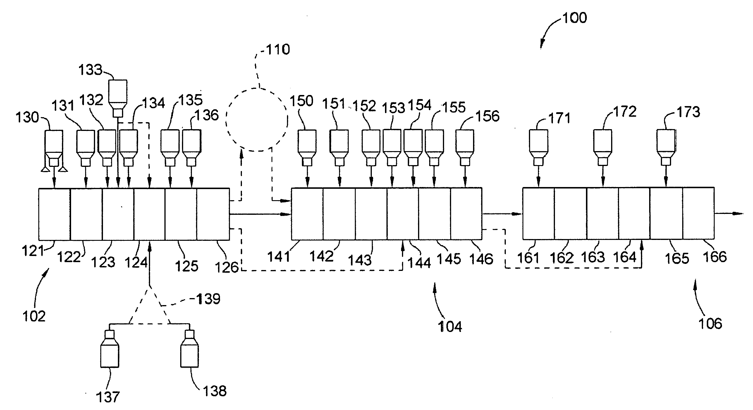
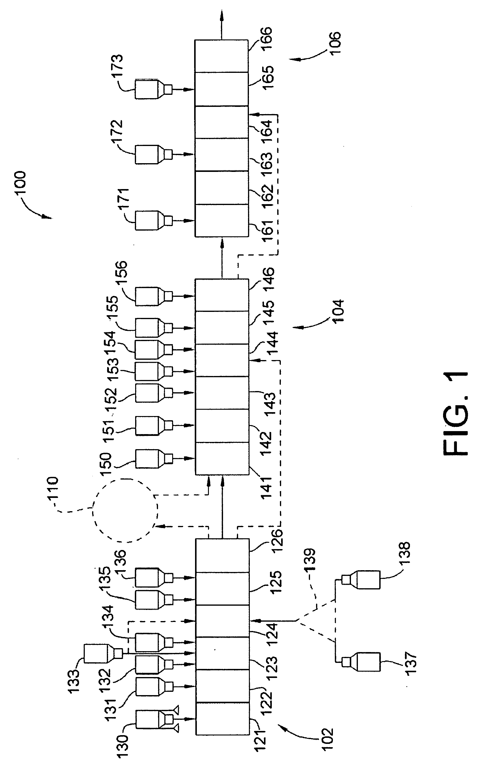
[0343]A third contemplated example relates to kitting and, particularly, kitting where a significant portion of bulk ingredients are added at a remote location. For reference in describing this example, reference will be made to mixing systems 100 of FIG. 1 and FIG. 13. Further, this example will use the gum structure of Example 6 of Table 3 and will employ a mixing process following Process 4 of Table 4 where the downstream mixing results in a finished gum composition (FG). The FGB of this FG forms approximately 30% by weight of the FG.
[0344]In this example, mixer 1 will take the form of continuous mixer 102 that is a high shear high temperature extruder used to compound the elastomeric portion of the gum base ingredients GBIx of the finished gum composition. The set of gum base ingredients GBIx added to mixer 1 will include the following ingredients. A high molecular weight elastomer in the form of butyl rubber is added at a rate of 10% by weight of the desired FGB along with a lo...
PUM
| Property | Measurement | Unit |
|---|---|---|
| Temperature | aaaaa | aaaaa |
| Temperature | aaaaa | aaaaa |
| Temperature | aaaaa | aaaaa |
Abstract
Description
Claims
Application Information