
Method of manufacturing pins of miniaturization chip module

a miniaturization chip and pin technology, applied in the direction of sustainable manufacturing/processing, final product manufacturing, printed circuit aspects, etc., can solve the problems of inferior heat dissipation, inferior liability, and difficulty in controlling the height of the solder ball, so as to improve the difficulty of controlling the solder ball, improve liability and heat dissipation, and improve the effect of manufacturing cos

Inactive Publication Date: 2009-06-25
UNIVERSAL SCI IND CO LTD
View PDF3 Cites 1 Cited by
  • Summary
  • Abstract
  • Description
  • Claims
  • Application Information

AI Technical Summary

Benefits of technology

[0006]It is an object of the invention to provide a method of manufacturing a miniaturization chip module, which improves the shortages of difficulty of controlling solder ball height in BGA solder ball implanting, and furthermore provides improved liability and heat dissipation with lower manufacturing cost.
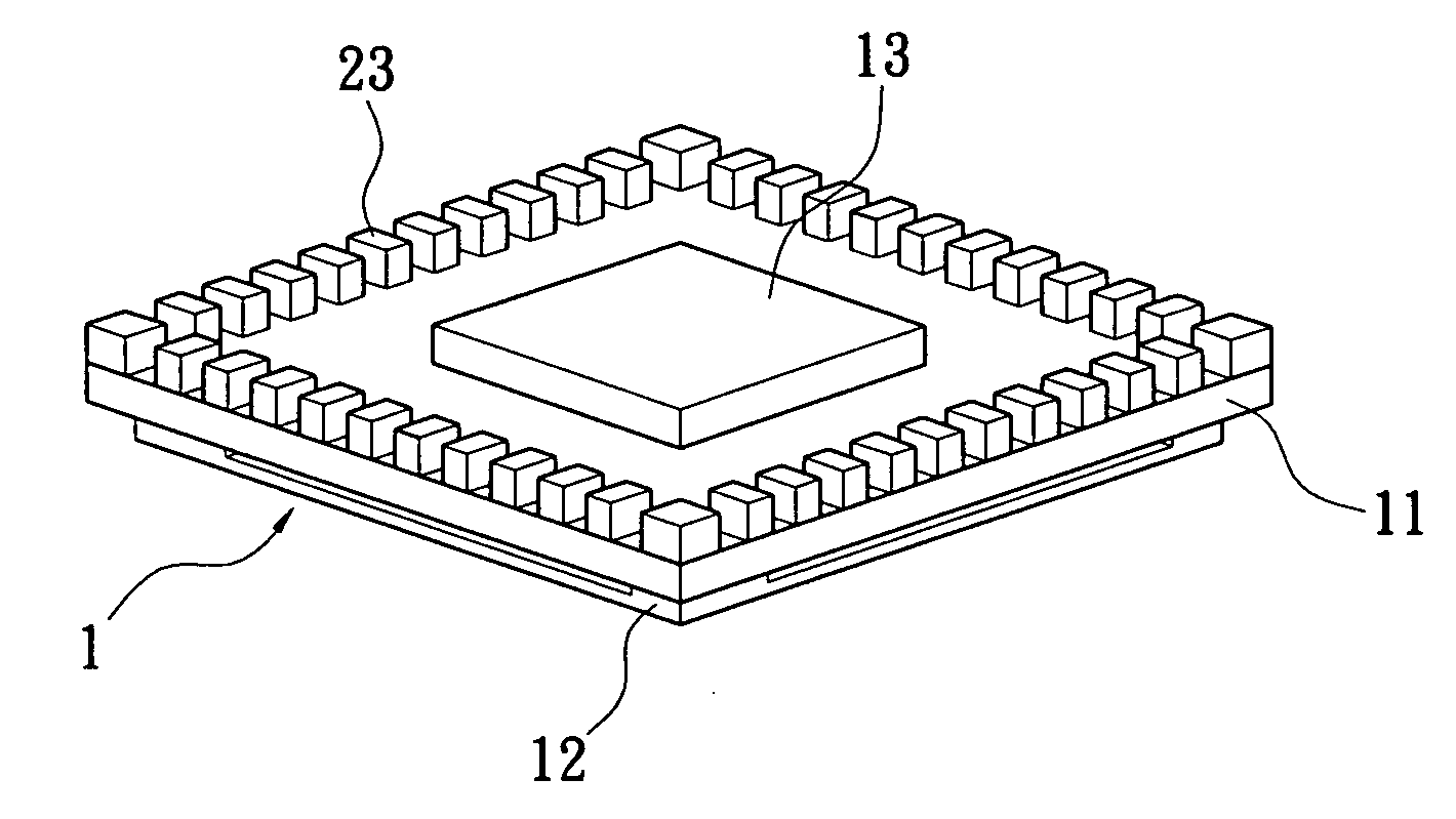
[0008]With formation of the metallic blocks of constant thickness, the prior problems such as collapse of solder balls and difficulty of controlling the ball height encountered in Ball Grid Array (BGA) can be overcome. In addition, the metallic blocks provide improved bonding reliability because their rectangular-column shape has a larger bonding area than solder balls. Furthermore, compared to via-holes in the lamination structure of the carrier board, the metallic blocks have larger thermal conducting areas and therefore offer improved heat dissipation with lower manufacturing cost.

Problems solved by technology

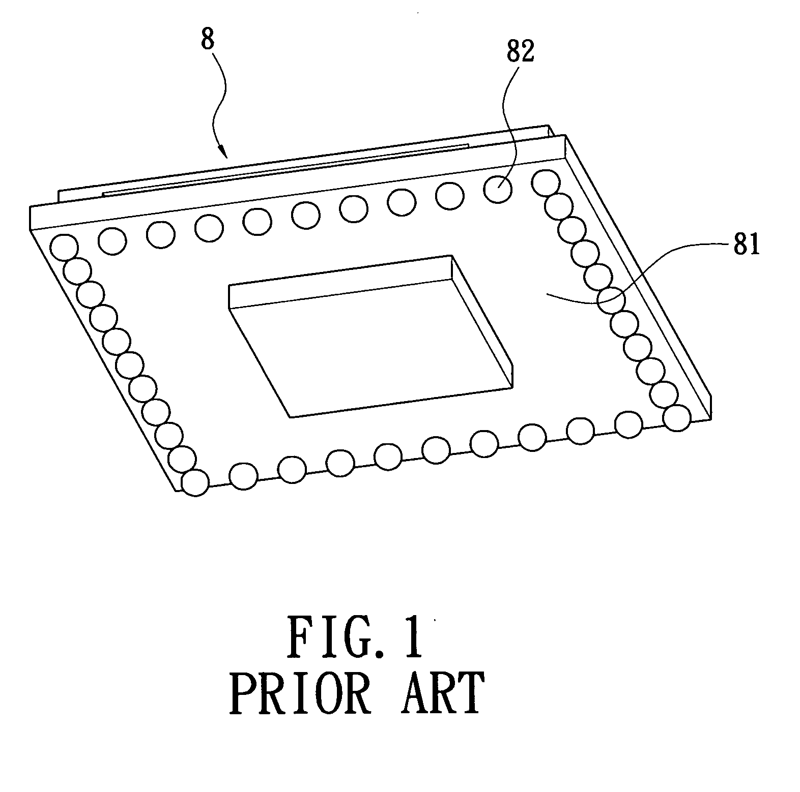
For example the solder balls tend to collapse, causing the difficulty of controlling solder ball height.
Besides, the solder balls easily delaminate from the main board 81 or frame they should firmly bonded to, resulting in inferior liability.
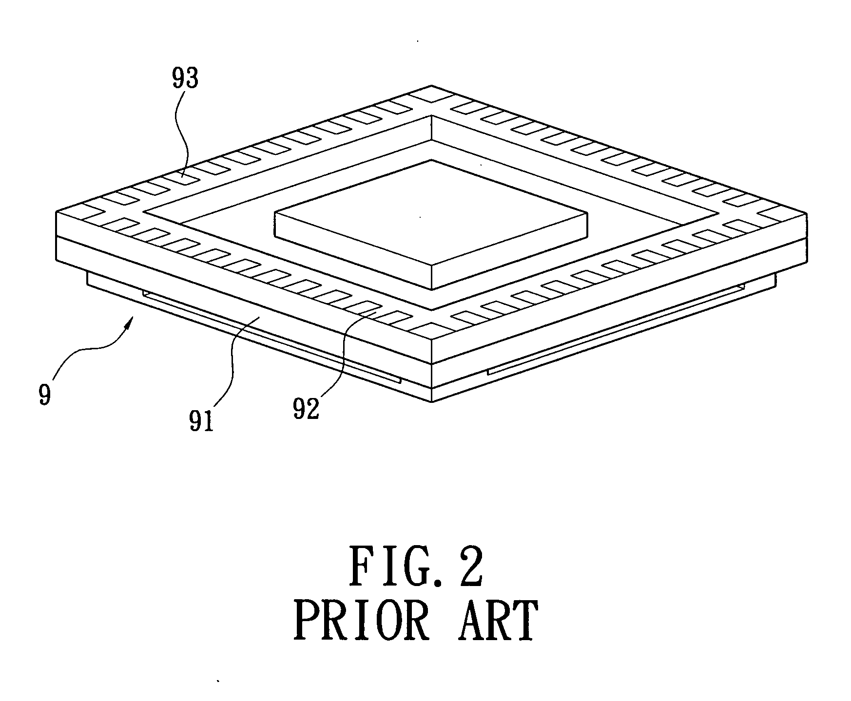
This type of I / O pins cost high and have inferior heat dissipation because the heat is only spread out through the via-holes of the interconnections.

Method used


Image

  • Method of manufacturing pins of miniaturization chip module
  • Method of manufacturing pins of miniaturization chip module
  • Method of manufacturing pins of miniaturization chip module

Examples


Embodiment Construction

[0016]Wherever possible in the following description, like reference numerals will refer to like elements and parts unless otherwise illustrated.

[0017]Referring to FIG. 3, according to one embodiment of the invention, a method of manufacturing a miniaturization chip module, particularly a method of manufacturing I / O pins of a miniaturization chip module is shown and will be illustrated in details as below.

[0018]A chip module 1, as shown in FIG. 4, is provided. The chip module is a surface mount technology (SMT) module in this embodiment. The chip module 1 has a substrate 11 on a front surface of which at least one first chip (not shown) and a metal cover 12 (as shown in FIG. 7 and FIG. 8) covering the chip are mounted. The first chip can be a surface-mounting device (SMD) chip for example. The metal cover 12 has bent legs which are welded onto the substrate 11 as a shield of the first chip for providing electromagnetic interference (EMI) effect. On a rear surface of the substrate 11...


PUM


Abstract

A method of manufacturing a miniaturization chip module includes steps of providing a chip module having a substrate, wherein the substrate has a plurality of bonding pads spaced on a rear surface of substrate; providing a lead frame including a plurality of spaced metallic studs, wherein the metallic studs are attached onto the bonding pads; and forming metallic blocks as I / O pins by removing a part of each metallic stud and a part of the lead frame which is not in contact with the substrate.

Description

BACKGROUND OF THE INVENTION[0001]1. Field of the Invention[0002]The invention generally relates to a method of manufacturing a miniaturization chip module, particularly a method of manufacturing input / output (I / O) pins of a miniaturization chip module.[0003]2. Description of the Related Art[0004]I / O pins for a prior Ball Grid Array (BGA) chip module package are solder balls as shown in FIG. 1. Referring to FIG. 1, a plurality of solder balls is mounted on a lower surface of a main board 81 of a surface mount technology (SMT) chip module 8 as the I / O pins. BGA is widely used because of low manufacturing cost but has some disadvantages. For example the solder balls tend to collapse, causing the difficulty of controlling solder ball height. Besides, the solder balls easily delaminate from the main board 81 or frame they should firmly bonded to, resulting in inferior liability.[0005]Referring to FIG. 2, via-holes in a prior laminated layered carrier board 92 mounted on a bottom of a mai...

Claims


Application Information

Patent Timeline
Patent Type & Authority Applications(United States)
IPC IPC(8): H01L21/60
CPCH01L21/4853H01L23/04H01L23/49811H01L23/552H01L2924/16152H05K2201/10924H01L2924/3025H05K3/3442H05K2201/10242H05K2201/10477H01L2924/167Y02P70/50
Inventor LI, KUAN-HSINGLIAO, KUO-HSIEN
Owner UNIVERSAL SCI IND CO LTD
Learn More