
Dual fuel can combustor with automatic liquid fuel purge

Inactive Publication Date: 2009-07-02
OPRA TECH
View PDF47 Cites 48 Cited by
  • Summary
  • Abstract
  • Description
  • Claims
  • Application Information

AI Technical Summary

Problems solved by technology

The need for these designs to have at least stand-by capability on liquid fuel has led to significant problems of functionality, optimization, and operational control.
The general problems in these designs stem from the use of multiple fuel injectors for the liquid fuel in an attempt to achieve the uniform distribution needed for the gaseous fuel system, which typically requires the use of multiple gas fuel ports distributed about the combustor head end.
The number of liquid fuel injectors required for this approach is large, complex and can be costly.
The necessary supply system and pipe work can be further complicated by the additional need to purge liquid fuel injectors and related fuel passages of the residual fuel that can cause blockage due to “coking” under engine thermal soak conditions.
The requirements for solenoid and stop valves to affect these requirements complicate the apparatus and add greatly to the cost.

Method used


Image

  • Dual fuel can combustor with automatic liquid fuel purge
  • Dual fuel can combustor with automatic liquid fuel purge
  • Dual fuel can combustor with automatic liquid fuel purge

Examples


Embodiment Construction

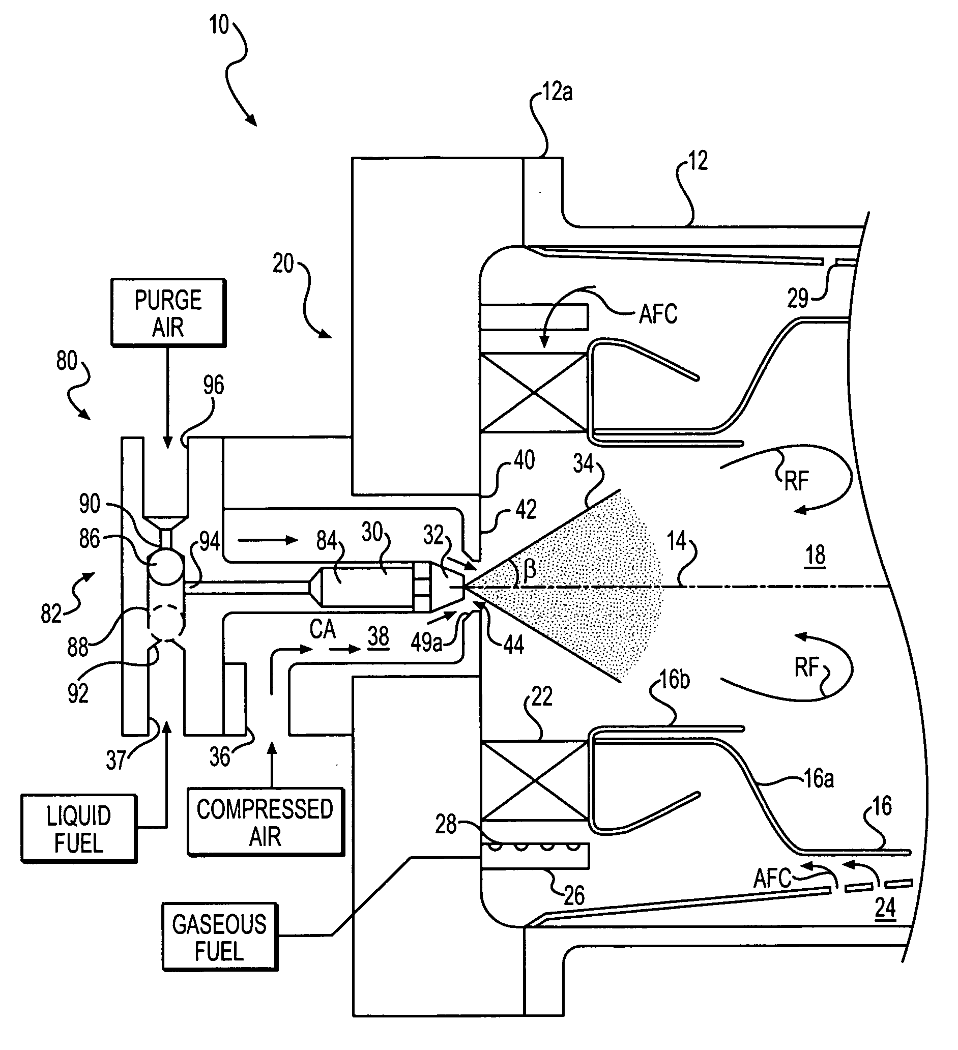
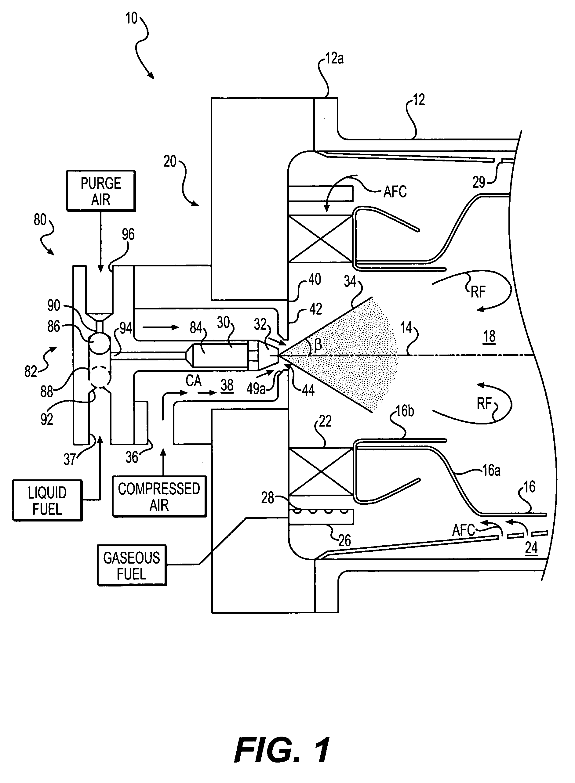
[0012]In accordance with the present invention, as broadly described herein, a dual fuel can combustor with automatic liquid fuel purge system includes a combustor housing having a longitudinal axis. As embodied herein, and with reference to FIG. 1, can combustor 10 includes housing 12, which is generally cylindrical with respect to longitudinal axis 14 although other general shapes can be used, as one of ordinary skill in the art would understand. Housing 12 includes a head end 12a.

[0013]Also in accordance with the present invention, as broadly described herein, the gas fired can combustor further includes combustor liner 16 disposed within, and radially spaced from, housing 12. Liner 16 is also substantially cylindrical about axis 14, but may include tapered, stepped, or “necked” portions of different diameters, such as liner end 16a including pre-chamber 16b, both shown longitudinally adjacent housing end 12a, in the FIG. 1 embodiment. Liner 16 can be fabricated with known high ...


PUM


Abstract

A lean, low NOx gas-fired can combustor having liquid fuel operation capability includes a housing, a combustor liner disposed within the housing and defining a combustion zone for combusting fuel with air, and a head assembly for joining the longitudinal housing and liner ends and for supporting swirler vanes that admit about 45-55% of a total combustor air flow to the combustion zone. The head assembly includes multiple gaseous fuel injection ports upstream of the swirler vanes, and a single liquid fuel injector positioned along the liner axis for directing atomized liquid fuel into the combustion zone. The head assembly further includes a heat shield disposed between the injector and the combustion zone, and the head assembly is configured to provide a flow of air for cooling the heat shield during all operations of the can combustor. The can combustor may also include apparatus for automatically purging the liquid fuel injector with compressed air, such as cooled compressed air from a gas turbine engine compressor stage. The apparatus includes a shuttle valve controller including a shuttle member biased by a first pressure towards a first position interconnecting the liquid fuel input to the liquid fuel injector inlet, while blocking compressed purging air flow, and biased by a second pressure towards a second position interconnecting the compressed purging air input to the liquid fuel injector inlet, while blocking liquid fuel flow.

Description

BACKGROUND OF THE INVENTION[0001]1. Field of the Invention[0002]The invention relates to low emissions gas-fired can combustors with additional liquid fuel injection for both dual fuel and bi-fuel operations. The invention also relates to an automatic purging system for can combustors having liquid fuel injection.[0003]2. Description of the Related Art[0004]Most recent can-type combustors designed to meet low NOx regulations have concentrated on the application of gaseous fuels and mainly natural gas. The need for these designs to have at least stand-by capability on liquid fuel has led to significant problems of functionality, optimization, and operational control. The general problems in these designs stem from the use of multiple fuel injectors for the liquid fuel in an attempt to achieve the uniform distribution needed for the gaseous fuel system, which typically requires the use of multiple gas fuel ports distributed about the combustor head end. The number of liquid fuel injec...

Claims


Application Information

Patent Timeline
IPC IPC(8): F02C3/24F02C7/12
CPCF23D17/002F23D2209/30F23R3/36F23R3/343F23R3/14
Inventor KORANEK, MICHAL
Owner OPRA TECH
Features
  • Generate Ideas
  • Intellectual Property
  • Life Sciences
  • Materials
  • Tech Scout
  • Unparalleled Data Quality
  • Higher Quality Content
  • 60% Fewer Hallucinations
Learn More