Jet engine with detachably arranged generator unit

a generator unit and jet engine technology, applied in the field of jet engines, can solve the problems of increasing the cost of initial placement assembly, installation options, maintenance and repair, and the mechanical and electrical connections of the generator with the jet engine and/or the aircraft are extremely difficult, and the maintenance effort and assembly effort is considerably increased. , to achieve the effect of minimizing the effort necessary and simple installation and removal

Active Publication Date: 2009-07-02
MTU AERO ENGINES GMBH
View PDF15 Cites 15 Cited by
  • Summary
  • Abstract
  • Description
  • Claims
  • Application Information

AI Technical Summary

Benefits of technology

[0011]Certain aspects of the present technology provide a jet engine with a generator unit, making possible simple installation and removal of the generator unit into and / or from the jet engine. Certain aspects of the present technology help to minimize the effort necessary to maintain the generator.

Problems solved by technology

The result is disadvantageous, as it leads to an increase in maintenance and assembly effort, which also causes a considerable increase in costs of initial placement assembly, maintenance and repair.
Problems occur with the presently known generator to shaft of the jet engine arrangements because the installation location of the generators are difficult to access, thereby causing problems, in particular in the area of the high pressure compressor, due to the limited installation conditions.
Even with a one-sided attachment of the generator to the low pressure shaft, the installation options, the maintenance and production of corresponding fluid, and the mechanical and electrical connections of the generator with the jet engine and / or with the aircraft are extremely difficult.
Because of this, the maintenance effort and the assembly effort are considerably increased, making replacement of the generator very complicated.
The mechanical connection between the engine shaft and the generator in most cases comprises a shaft coupling, which also requires a complicated installation and / or removal.

Method used


Image

  • Jet engine with detachably arranged generator unit
  • Jet engine with detachably arranged generator unit
  • Jet engine with detachably arranged generator unit

Examples


Embodiment Construction

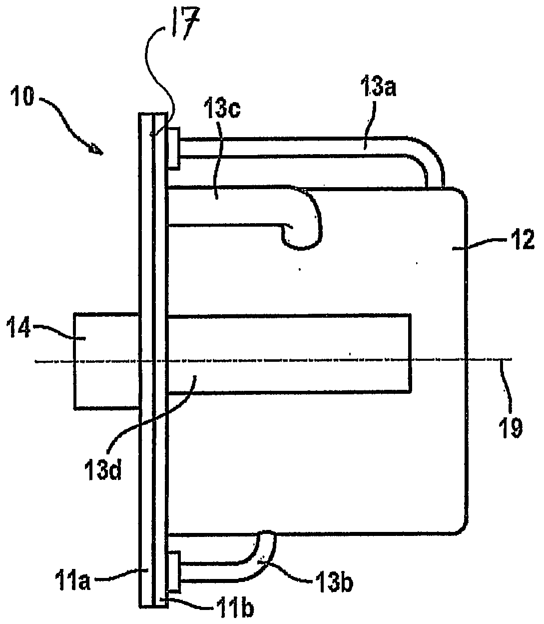
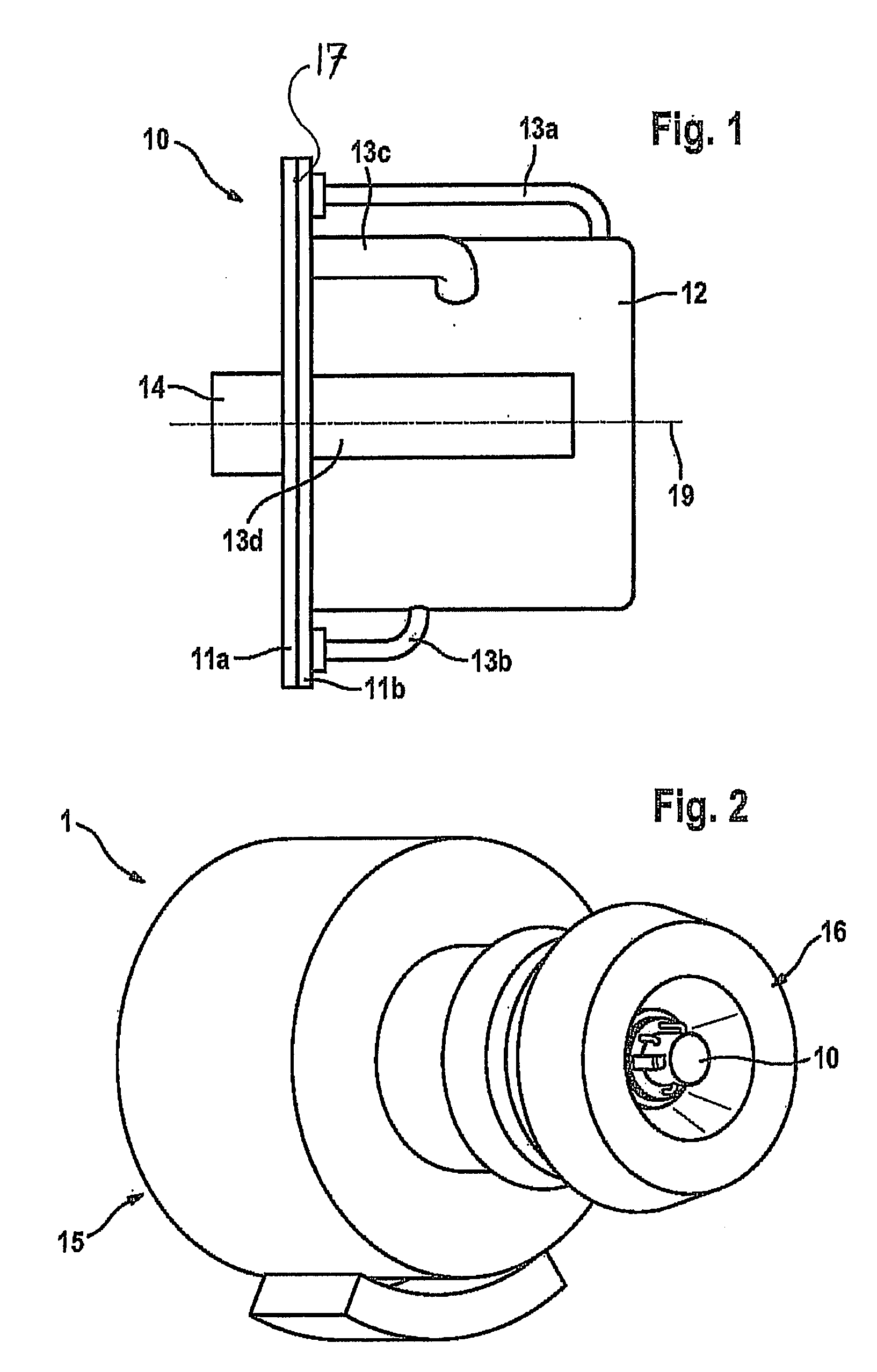
[0019]Certain embodiments of the present technology provide an electrical generator unit having a locating plate and a generator, whereby the generator unit is mounted detachably on the locating plate on the engine side.

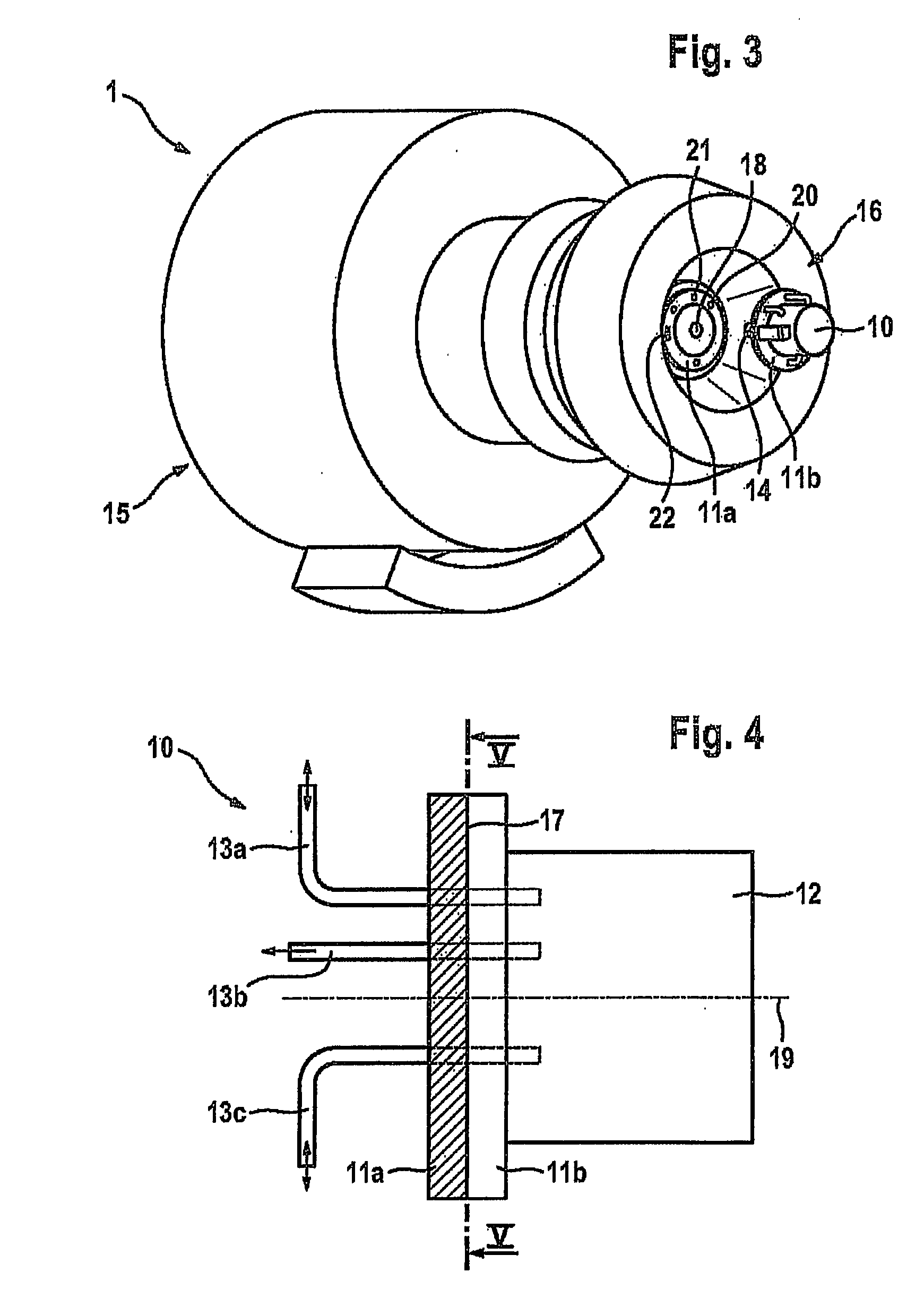
[0020]The present technology is based on the concept that the generator unit for power generation has an interface that connects the generator unit tightly with the locating plate on the engine side forming the other half of the multi-function coupling. On the other side, the generator shaft is coupled to the turbine shaft by way of a direct or indirect (intermediate gear) connection. For this purpose, the locating plate on the engine side is provided with a hole that is larger than the generator shaft. For simpler installation / removal of the generator shaft with the locating plate on the engine side, at least one centering pin engages between the two units to be connected before any of the other elements engage with each other.

[0021]The generator unit can be arrange...


PUM


Abstract

The present technology generally relates to jet engines, in particular for an aircraft, having at least one turbine shaft on which at least one compressor and a turbine are arranged, and a housing extends over the lateral surfaces of the jet engine, wherein furthermore at least one electrical generator unit for generating electricity is arranged on at least one turbine shaft, wherein the electrical generator unit has a locating plate and a generator, wherein the generator unit is detachably mounted on the engine-side locating plate. Therefore, a jet engine having a generator unit is provided which permits simple installation, removal and servicing of the generator unit in or out of the jet engine.

Description

RELATED APPLICATIONS[0001]This application is a continuation of International Application Serial No. PCT / DE2007 / 000567 (International Publication Number WO 2007 / 112726), having an International filing date of Mar. 29, 2007 entitled “Strahltriebwerk Mit Lösbar Angeordneter Generatoreinheit” (“Jet Engine with Detachably Arranged Generator Unit”). International Application No. PCT / DE2007 / 000567 claimed priority benefits, in turn, from German Patent Application No. 10 2006 015 639.0, filed Apr. 4, 2006. International Application No. PCT / DE2007 / 000567 and German Application No. 10 2006 015 639.0 are hereby incorporated by reference herein in their entireties.FEDERALLY SPONSORED RESEARCH OR DEVELOPMENT[0002][Not Applicable]MICROFICHE / COPYRIGHT REFERENCE[0003][Not Applicable]BACKGROUND OF THE INVENTION[0004]The presently described technology relates to a jet engine. In particular, the present technology relates to jet engines for an aircraft.[0005]Jet engines for an aircraft often have gen...

Claims


Application Information

Patent Timeline
Patent Type & Authority Applications(United States)
IPC IPC(8): F02C6/18F02C7/20
CPCF01D15/10F02C7/32H02K5/26F05D2230/61F05D2230/60F05D2220/76H02K7/1823
Inventor GOTZ, WERNERHERRMANN, HUBERT
Owner MTU AERO ENGINES GMBH
Why Eureka
Try Eureka