Charge pumping circuit with decreased current consumption

a charge pump and current consumption technology, applied in the direction of electric variable regulation, process and machine control, instruments, etc., can solve the problems of large amount of current consumed, and extremely high peak current, so as to improve the peak current, reduce the number of simultaneously operating charge pumps, and improve the layout of the present invention

Active Publication Date: 2009-07-02
SK HYNIX INC
View PDF5 Cites 1 Cited by
  • Summary
  • Abstract
  • Description
  • Claims
  • Application Information

AI Technical Summary

Benefits of technology

[0021]According to the present invention, it is possible to improve the peak current since the number of simultaneously operating charge pumps is reduced. Also, the layout of the present invention is improved, since a sufficient high-voltage pumping current can be provided with a smaller number of pumps.

Problems solved by technology

If large numbers of high-voltage pumps operate at the same time, large amount of current is consumed, and thus the peak current is extremely high.
When a charge pump of high voltage Vpp is utilized (thereby resulting in a large amount of consumed current), current from the external supply voltage VDD is also consumed, and therefore in a typical circuit for pumping the high voltage Vpp the operational characteristics of a DRAM are deteriorated.
Further, the large number of high-voltage pumps configured in the typical circuit of FIG. 1 has a disadvantage in terms of the layout of the circuit.

Method used


Image

  • Charge pumping circuit with decreased current consumption
  • Charge pumping circuit with decreased current consumption
  • Charge pumping circuit with decreased current consumption

Examples


Embodiment Construction

[0026]Hereinafter, preferred embodiments of the present invention will be described in detail with reference to the accompanying drawings.

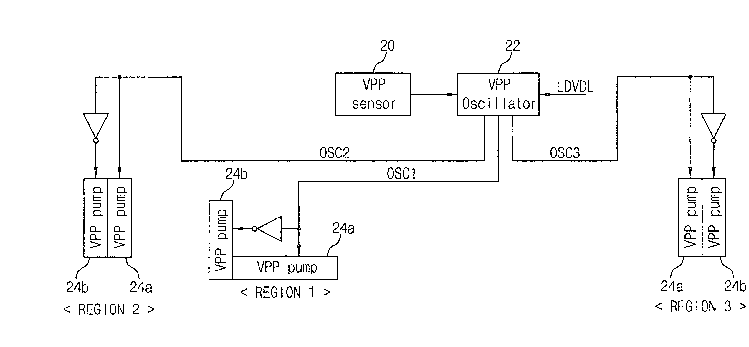
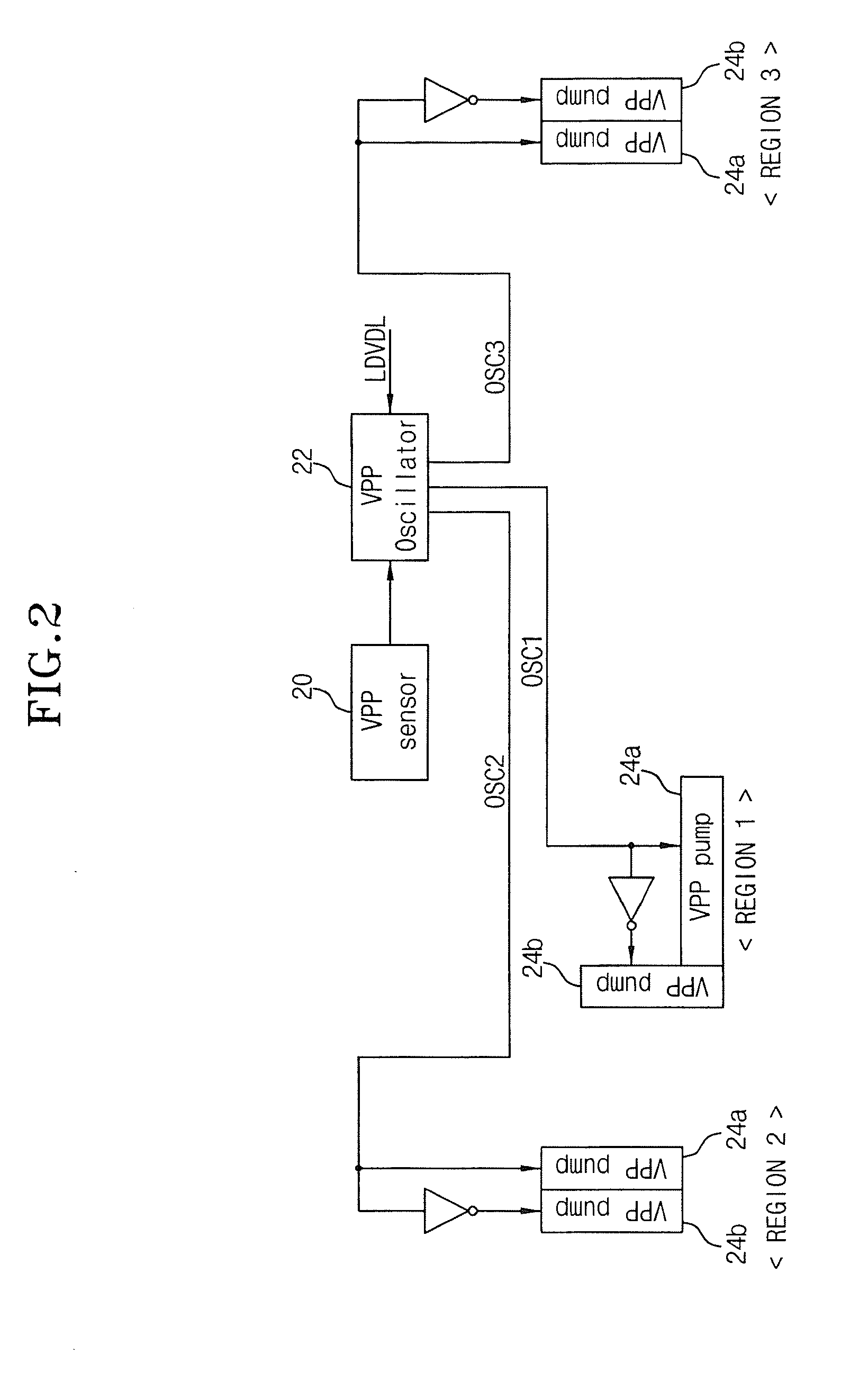
[0027]The present invention is constructed in such a way as to allow high-voltage pumps to be sequentially pumped in each region by providing clock signals having sequentially shifted phases to high-voltage pumps disposed in various regions for each bank in a DRAM.

[0028]Referring to FIG. 2, the charge pumping circuit shown in FIG. 2 is constructed with respect to high voltage as an example; however, the charge pumping circuit according to the present invention can be also used for other voltages such as a back-bias voltage.

[0029]The charge pumping circuit according to an embodiment of the present invention includes a high voltage sensor 20, a high voltage oscillator 22, and a plurality of high-voltage pumps 24a, 24b.

[0030]The high voltage sensor 20 detects the level of a high voltage Vpp and generates a control signal if the level of the high vol...


PUM


Abstract

A charge pumping circuit consumes less current by reducing the number of charge pumps operating simultaneously. The charge pumping circuit includes a voltage sensor that detects a level of a high voltage and outputs a control signal based on the detection result. An oscillator provides an oscillating clock signal in response to the control signal of the voltage sensor, and the oscillator sequentially outputs the clock signal as a plurality of clock signals having shifted phases A plurality of high-voltage pumps are disposed in a plurality of regions to pump the high voltage in response to the clock signals and a different phase is designated for each region.

Description

CROSS-REFERENCE TO RELATED APPLICATIONS[0001]The present application claims priority to Korean patent application number 10-2008-0000290 filed on Jan. 2, 2008, which is incorporated herein by reference in its entirety.BACKGROUND OF THE INVENTION[0002]The present invention relates to a charge pumping circuit, and more particularly to a charge pumping circuit in which the layout and current consumption are improved by reducing the number of simultaneously operating charge pumps in a DRAM.[0003]Typically, during the operation of a DRAM various voltages are utilizing. The DRAM is equipped with a charge pumping circuit which detects the level of a supplied voltage and which pumps the voltage in order to maintain a predetermined voltage level.[0004]A DRAM cell can use a high voltage Vpp or a back bias voltage Vbb upon operation of the cell, and the DRAM cell is equipped with a distinct charge pumping circuit for the purpose of supplying the high voltage Vpp or the back bias voltage Vbb.[0...

Claims


Application Information

Patent Timeline
Patent Type & Authority Applications(United States)
IPC IPC(8): G05F1/10
CPCG11C5/145H02M2001/008H02M3/073H02M1/32H02M1/008G11C5/14G11C11/4074
Inventor KIM, JONG SAMLEE, JONG CHERN
Owner SK HYNIX INC
Why Eureka
Try Eureka