Switching power supply and control circuit thereof

A technology for controlling circuits and compensating current, which is applied in the direction of control/regulation systems, electrical components, and adjustment of electrical variables. It can solve problems such as loop instability, inability to effectively compensate output cable voltage drop errors, and output voltage deviations. Achieve the effects of improving stability, improving output voltage curve, and reducing output voltage

Active Publication Date: 2021-10-01
HANGZHOU SILAN MICROELECTRONICS
View PDF3 Cites 1 Cited by
  • Summary
  • Abstract
  • Description
  • Claims
  • Application Information

AI Technical Summary

Problems solved by technology

[0003]However, in the existing switching power supply control process, the switching frequency is controlled by using an exponential function. The interference of factors may easily cause loop instability
[0004] Further, the use of switching frequency for line loss compensation cannot effectively compensate sampling errors, output cable voltage drop errors, loop DC gain errors, and sampling position shifts, etc. Output voltage deviation due to various influences

Method used


Image

  • Switching power supply and control circuit thereof
  • Switching power supply and control circuit thereof
  • Switching power supply and control circuit thereof

Examples


Embodiment Construction

[0086] Various embodiments of the present invention will be described in more detail below with reference to the accompanying drawings. In each of the drawings, the same elements are expressed by the same or similar reference numerals. For the sake of clarity, the various parts in the drawings are not drawn.

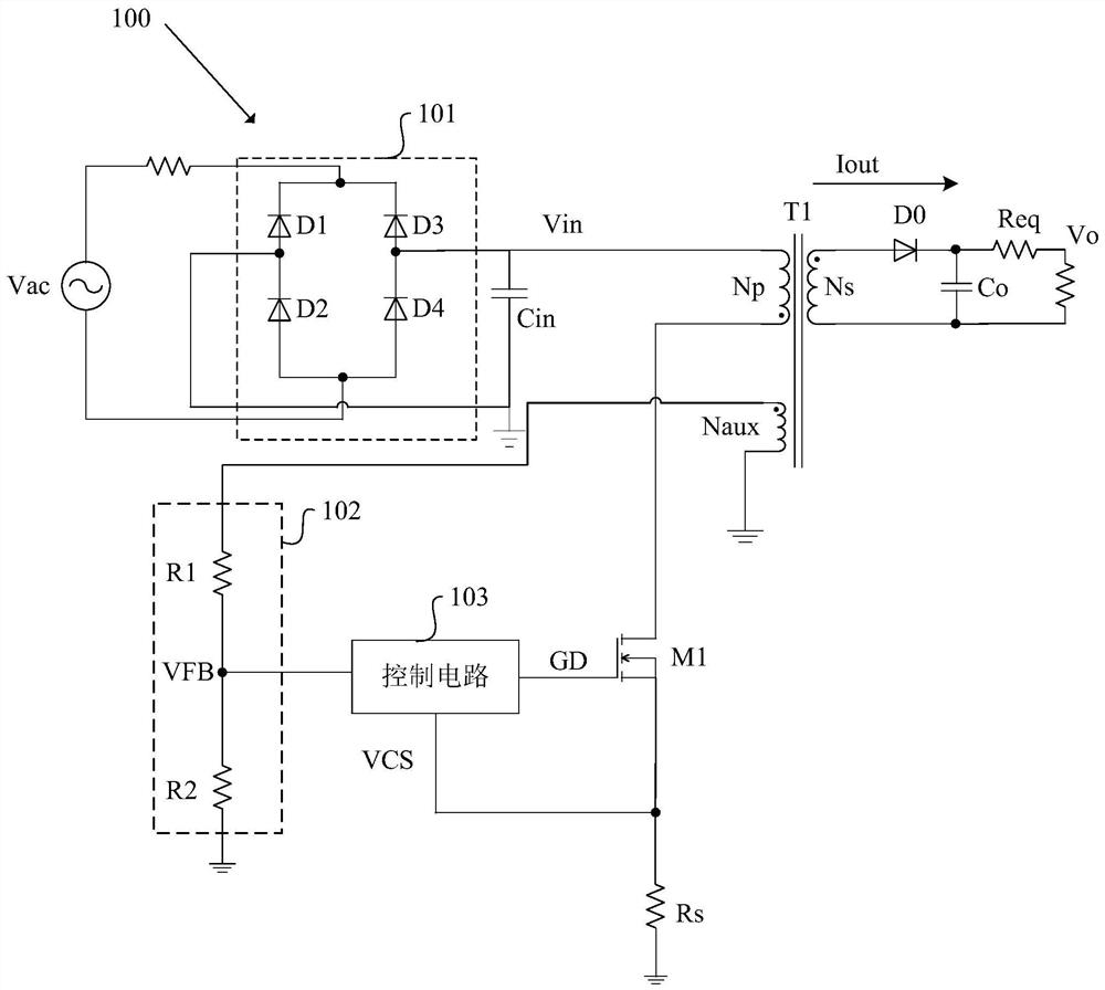
[0087] figure 1 A schematic diagram showing the switching power supply in which the original edge control is known. like figure 1 As shown, the switching power source 100 includes a transformer T1, a switching tube M1, a current sampling resistor RS, a rectifier bridge 101, an input capacitor Cin, a voltage feedback circuit 102, a control circuit 103, a continuation stream of the secondary side of the transformer T1. Diode D0, output capacitor CO, and an equivalent resistance of output cable.

[0088] The rectifier bridge 101 includes diodes D1 to D4. The two inputs of the rectifier bridge 101 receive AC input voltage Vac from the external AC power source. The input capacit...


PUM


Abstract

The invention discloses a switching power supply and a control circuit thereof. The control circuit comprises: a demagnetization detection module for obtaining a demagnetization time and a sampling time according to a voltage feedback signal; a frequency generation module for generating a ramp signal according to the demagnetization time, an oscillation signal, a first voltage sampling signal and a driving signal of a switching tube; a conduction control module for sampling and holding the voltage feedback signal to obtain a second voltage sampling signal, generating an error signal according to the second voltage sampling signal and a reference voltage, and generating a conduction signal according to the error signal and the ramp signal; a turn-off signal generation module for generating a turn-off signal according to the current sampling signal and the error signal; and a line loss compensation module for generating compensation current according to the demagnetization time, the sampling time and the error signal and superposing the compensation current to the conduction control module. According to the invention, output voltage deviation caused by various influences such as output cable voltage drop, loop direct-current gain error, sampling position movement and the like can be compensated, and an output voltage curve is improved.

Description

Technical field [0001] The present invention relates to the field of switching power supply, and in particular, to a switching power source and a control circuit thereof. Background technique [0002] The switching power source controlled by the primary side can obtain the voltage feedback signal associated with the output voltage using the auxiliary winding of the transformer, so that the electronic component such as optocoupler and precision voltage source such as the original side can be saved. Signal feedback path. The principal-controlled switching power supply is easy to form a modular and miniaturized integrated circuit, which has been widely used for various charging power supplies for electronic digital products such as mobile phones, tablets and portable media players, and for driving LEDs (LEDs). In the power supply. [0003] However, during the existing switching power supply control, the index function is used to control the switching frequency. When light load and c...

Claims


Application Information

Patent Timeline
Patent Type & Authority Applications(China)
IPC IPC(8): H02M3/335
CPCH02M3/33523
Inventor 张钦阳洪益文廖小军詹桦
Owner HANGZHOU SILAN MICROELECTRONICS
Why Eureka
Try Eureka