Static eliminator

Active Publication Date: 2009-07-02
KEYENCE
View PDF3 Cites 9 Cited by
  • Summary
  • Abstract
  • Description
  • Claims
  • Application Information

AI Technical Summary

Benefits of technology

[0008]An object of the present invention is to provide a static eliminator capable of accurately detecting a contamination condition of a discharge electrode.
[0009]According to a first aspect of the present invention, the above-mentioned technical object is achieved by providing a static eliminator, which applies a high voltage to a discharge electrode to generate ions so as to eliminate static electricity of a workpiece, the eliminator having: an ion current detection device which detects an ion current between a discharge electrode and a frame ground; an ion generation control device which adjusts a voltage to be applied to the discharge electrode such that the ion current detected by the ion current detection device is a prescribed ion balance target value; a target value change device which changes the ion balance target value to a target value offset to such a degree as not to affect the ion balance of the workpiece; and an electrode contamination detection device which detects contamination of the discharge electrode in accordance with the quality of follow-up performance of the control when the ion balance target value is changed by the target value change device.
[0010]According to a second aspect of the present invention, the above-mentioned technical object is achieved by providing a static eliminator, which applies a high voltage to a discharge electrode to generate ions so as to eliminate static electricity of a work

Problems solved by technology

In a case where contamination of the discharge electrode is detected by means of the ion current between the discharge electrode and the ground electrode (opposing electrode) around the discharge electrode, for example when a capacious workpiece is present in the vicinity of the static eliminator, the ion current flowing between the discharge

Method used


Image

  • Static eliminator
  • Static eliminator
  • Static eliminator

Examples


Example

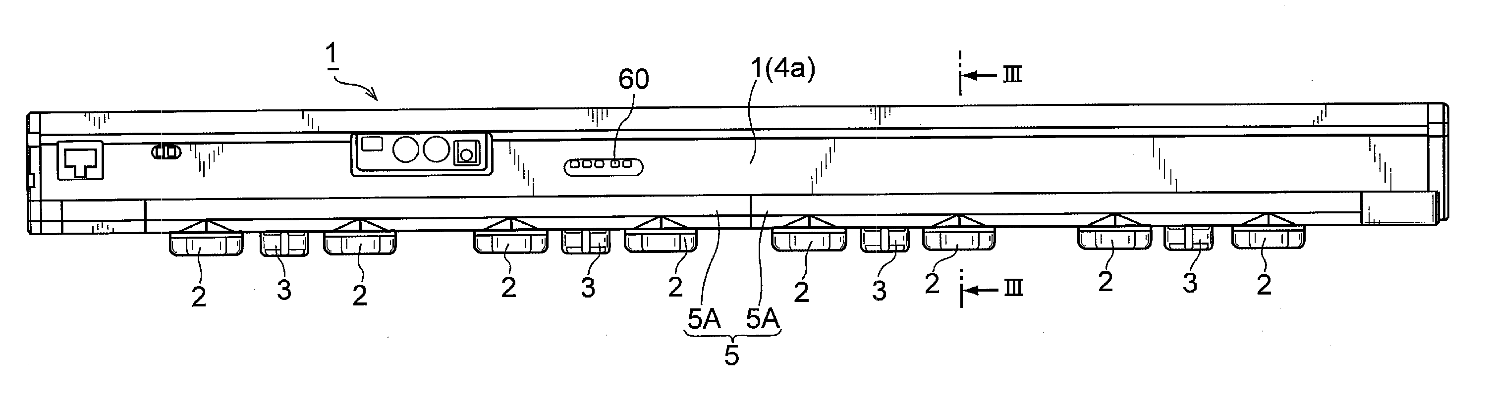
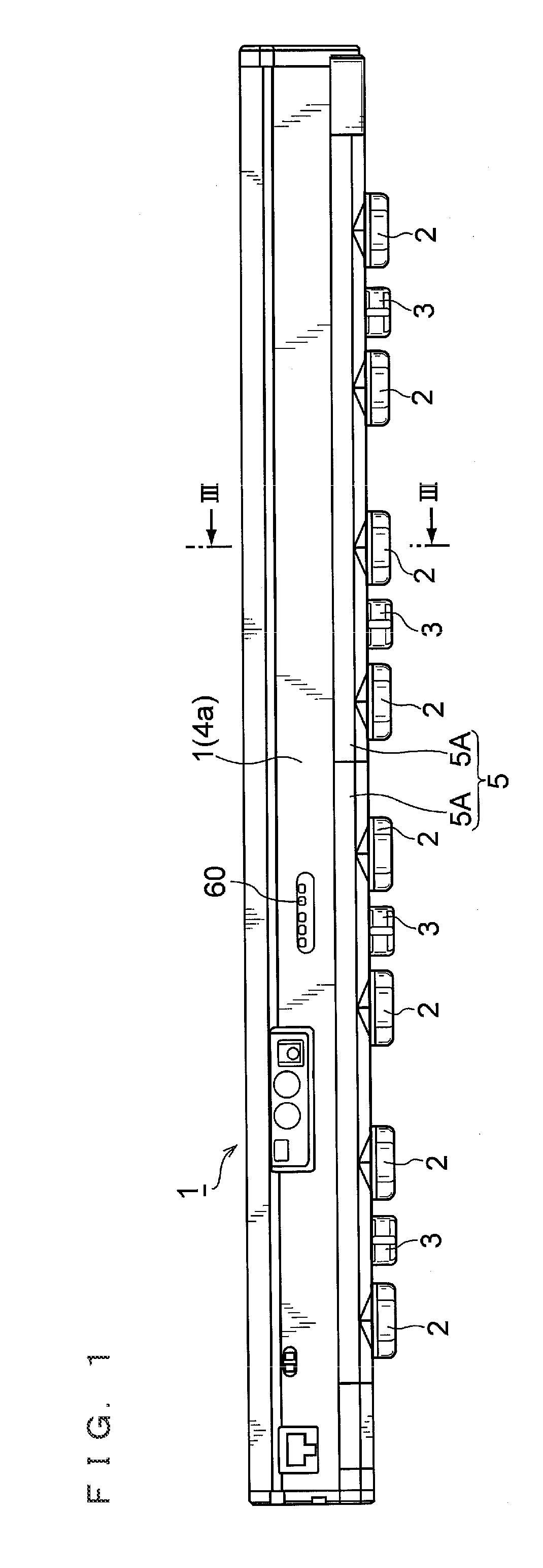
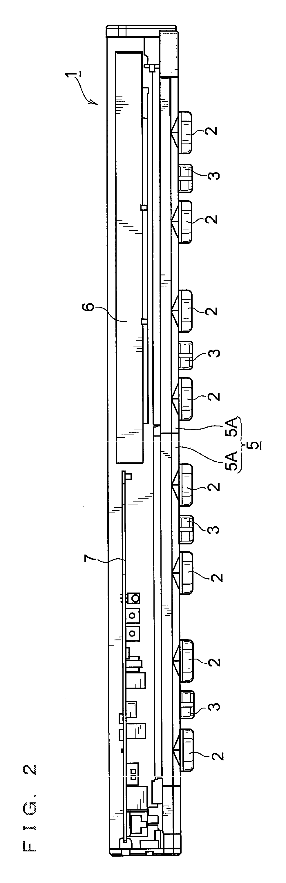
[0043]An embodiment of the present invention will be described in detail below with reference to the accompanying drawings. FIG. 1 is a side view of a static eliminator of the embodiment. In a static eliminator 1, eight main discharge electrode units 2 and four additional discharge electrode units 3 are mounted in a plurality of number in a longitudinally spaced condition on the bottom surface of a case 1a with a long external outline. It is to be noted that the four additional discharge electrode units 3 are attached and detached according to the user's option, and the configuration of this additional discharge electrode unit 3 is approximately equal to a basic configuration of the main discharge electrode unit 2. The difference between the main discharge electrode unit 2 and the additional discharge electrode unit 3 will be described later.

[0044]The outer case 4 for covering the upper half of the static eliminator 1 has a closed-top open-end cross-sectionally inverted U shape with...


PUM


Abstract

There is provided a static eliminator for accurately detecting a contamination condition of a discharge electrode, in which a target value as a target frame ground current value is changed from, for example, zero as a reference alternately to the plus side and the minus side to such a degree as not to affect the ion balance of a workpiece, and the follow-up time, namely a phase delay, with respect to the change in target value differs depending on the contamination condition of the discharge electrode, and becomes longer with the progress of the contamination, and by use of this characteristic, a plurality of thresholds are prepared and compared with a detected frame ground current value, so as to detect the contamination condition of the discharge electrode.

Description

CROSS-REFERENCE TO RELATED APPLICATIONS[0001]The present application claims foreign priority based on Japanese Patent Application No. 2007-341094, filed Dec. 28, 2007, the contents of which is incorporated herein by reference.BACKGROUND OF THE INVENTION[0002]1. Field of the Invention[0003]The present invention relates to a static eliminator used for eliminating static electricity of a workpiece, and more specifically relates to a static eliminator capable of accurately detecting a contamination condition of a discharge electrode included in the static eliminator.[0004]2. Description of the Related Art[0005]For the purpose of eliminating static electricity of a workpiece, a corona discharge type static eliminator has often been used. Typically, in a static eliminator having a long bar shape, a plurality of discharge electrodes are mounted in a longitudinally spaced condition, and a high voltage is applied to these discharge electrodes to generate an electric field between the dischar...

Claims


Application Information

Patent Timeline
IPC IPC(8): H05F3/06
CPCH01T23/00H05F3/04
Inventor HASHIMOTO, TADASHI
Owner KEYENCE
Why Eureka
Try Eureka