Planar light source, display device and method for manufacturing the same

a technology of display device and light source, which is applied in the direction of sparking plugs, lighting and heating apparatus, instruments, etc., can solve the problems of increasing distance, color and uneven luminous intensity uneven color and uneven luminous intensity of light-emitting elements must be fully restrained, so as to effectively restrain color and uneven luminous intensity, the effect of reducing the distance between a backlight and a display panel

Inactive Publication Date: 2009-07-02
SHARP KK
View PDF15 Cites 17 Cited by
  • Summary
  • Abstract
  • Description
  • Claims
  • Application Information

AI Technical Summary

Benefits of technology

[0012]An object of the present invention is to provide a planar light source which can effectively restrain unevenness of color and unevenness of luminous intensity, and to provide a flat display device in which unevenness of color and unevenness of luminous intensity are restrained even if the distance between a backlight and a display panel is reduced.

Problems solved by technology

A method thus using three-color LEDs has the advantage of widening a color reproducibility region of a liquid crystal display device, whereas has the disadvantage of a necessity of increase in the distance between the backlight and the liquid crystal display panel so that a good mixture of the three colors is realized in the liquid crystal display panel.
However, the LED illumination device disclosed in Patent Document 2 still has the following problems to be solved.
First, in a planar light source in which light-emitting elements are provided two-dimensionally, unevenness of color and unevenness of luminous intensity must be fully restrained.
Second, when the planar light source in which the light-emitting elements are provided two-dimensionally is used as a backlight of a liquid crystal display device or the like, unevenness of color and unevenness of luminous intensity of the light-emitting elements must be fully restrained in a display panel provided near a backlight.

Method used


Image

  • Planar light source, display device and method for manufacturing the same
  • Planar light source, display device and method for manufacturing the same
  • Planar light source, display device and method for manufacturing the same

Examples


embodiment 1

[0050]Explained in the present embodiment is (i) a planar light source in which light-emitting elements are provided in accordance with a predetermined planar arrangement rule so that unevenness of chromaticity and unevenness of luminous intensity are restrained and (ii) a display device using the planar light source.

[0051](Light-Emitting Element)

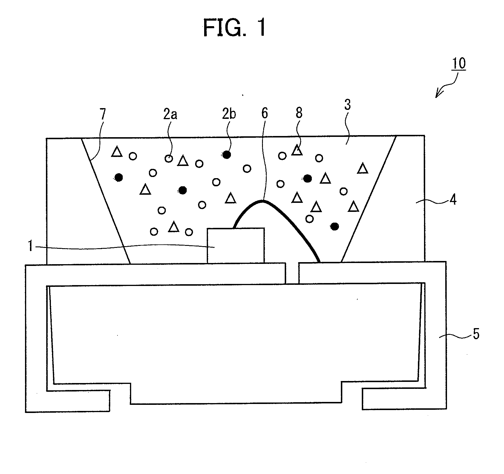
[0052]FIG. 1 is a cross-sectional view of a light-emitting element 10 of the present embodiment. In the light-emitting element 10, a semiconductor light-emitting element 1 is die-bonded to a frame 4 including a concavity having a reflection surface 7 and is sealed by a resin 3. Fluorescent substances 2 are, in advance, dispersed in the resin 3. The light-emitting element 10 is designed so that (i) when primary light emitted from the semiconductor light-emitting element 1 passes through the resin 3, the fluorescent substances 2 are partially excited by the primary light and are converted into secondary light, and (ii) the primary light and t...

embodiment 2

[0084]The Embodiment 1 deals with a planar light source in which light-emitting elements belonging to respective chromaticity groups are provided at regular intervals in a transverse direction in accordance with the planar arrangement rule 1, 2 or 3. However, the present embodiment deals with a case where pairs of two light-emitting elements belonging to different chromaticity groups are provided so as to be adjacent to each other in accordance with a planar arrangement rule 4 or 5 so that in-plane unevenness of chromaticity is reduced. Further, the present embodiment deals with a liquid crystal display device 90 including a planar light source 80 having the above arrangement.

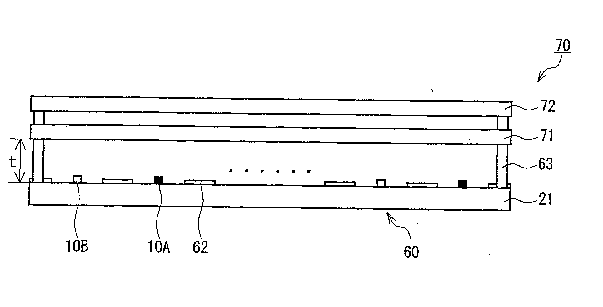
[0085]FIG. 12 (a) and FIG. 12 (b) are a top view and a cross-sectional view, respectively, showing an arrangement of a display device. The display device 90 includes the planar light source 80, a diffusion plate 91 provided so as to keep a distance t from the planar light source 80, and a liquid crystal display...

embodiment 3

[0110]Embodiment 3 deals with a displaying method for correcting chromaticity of a planar light source when the chromaticity differs from target white chromaticity.

[0111](Offset Correction of Chromaticity by a Liquid Crystal Display Device)

[0112]FIG. 21 is a chromaticity diagram for explaining adjustment of the chromaticity of a liquid crystal display device. Plotted in FIG. 21 are target chromaticity W, and chromaticity WA and WB obtained when white colors are displayed by liquid crystal display device A and B, respectively, which are two samples of the liquid crystal display device 90.

[0113]At least because of the reason that mold lots of light-emitting elements constituting planar light sources which the liquid crystal display devices A and B include, respectively, are different from each other, and other reasons, the light-emitting elements to be used have different chromaticity distributions. Therefore, the chromaticity WA and WB do not coincide with the target chromaticity W.

[...


PUM

PropertyMeasurementUnit
wavelengthaaaaaaaaaa
emission peak wavelengthaaaaaaaaaa

Abstract

Light-emitting elements are divided into chromaticity groups on the basis of their chromaticity. In a planar light source, light-emitting elements selected from two of the chromaticity groups are alternately provided in a longitudinal direction and in a transverse direction, respectively. The two chromaticity groups are substantially equally away from a target chromaticity in directions reverse to each other. Further, pairs of two of the light-emitting elements belonging to the two chromaticity groups which are separated from each other, are provided so that distances d2 at which two of the light-emitting elements in each of the pairs are provided are less than distances d1 at which the pairs are provided.

Description

[0001]This Nonprovisional application claims priority under U.S.C. § 119(a) on Patent Application No. 338331 / 2007 filed in Japan on Dec. 27, 2007, the entire contents of which are hereby incorporated by reference.FIELD OF THE INVENTION[0002]The present invention relates to (i) a planar light source using an LED which planar light source can be for use in, for example indicator, illumination or displaying, (ii) a display device such as a liquid crystal display device using the planar light source and (iii) a method for manufacturing the planar light source and the display device.BACKGROUND OF THE INVENTION[0003]With a rapid progress of LED techniques, especially, techniques for a blue LED (light-emitting diode) which is a III nitride semiconductor light-emitting element, a white LED (hereinafter referred to as “light-emitting element”) which is a combination of a blue LED and a fluorescent substance (e.g. yellow fluorescent substance) has been put into practical use. The white LED ha...

Claims


Application Information

Patent Timeline
Patent Type & Authority Applications(United States)
IPC IPC(8): G02F1/13357H01J61/00H01J9/42F21V9/40
CPCG02F1/133603G02F1/133611G02F1/133609
Inventor KAWASAKI, OSAMUMORIMOTO, TAIJIWATANABE, MASANORI
Owner SHARP KK
Why Eureka
Try Eureka