Surface light source device and liquid crystal display device

Active Publication Date: 2016-02-25
MITSUBISHI ELECTRIC CORP
View PDF4 Cites 9 Cited by
  • Summary
  • Abstract
  • Description
  • Claims
  • Application Information

AI Technical Summary

Benefits of technology

This patent describes a surface light source device and a liquid crystal display device that can display high-quality images using two types of light sources that have different light emission characteristics. The device includes a first light source that emits light in one direction and a second light source that emits light in the same direction as the first light source. Part of the first and second light is reflected by a reflecting bar and is extended in the same direction, resulting in illumination light with a uniform planar distribution. The reflected light is also mixed with color in the reflecting member to prevent color unevenness. The residual part of the first and second light is transmitted through the opening portion, ensuring even light intensity distribution. This device allows for the efficient use of light and results in a high-quality image display with a simple structure.

Problems solved by technology

For this reason, if the color purity of the display color is to be increased, there is a problem in that a quantity of light transmitted through the color filter is decreased, resulting in reduction in a luminance.
If the color purity is to be increased in a wavelength region of 630 to 640 nm which is preferable as pure red in the red color, therefore, there is a problem in that the quantity of transmitted light is extremely reduced, resulting in significant reduction in a luminance.
However, the laser is a light source having a very small divergence angle, and is difficult to have equivalent expansion to LED light with a large divergence angle by a lens and the light emitting diode device through the same method as the LED.
When distribution of a laser beam is different from that of the LED light over a display surface, luminance unevenness and color irregularity are caused.
It is difficult to create a uniform surface light source with the same structure.
When two types of light sources are each caused to have structures for creating surface light sources, moreover, the structures are made complicated so that a manufacturing cost is increased.

Method used


Image

  • Surface light source device and liquid crystal display device
  • Surface light source device and liquid crystal display device
  • Surface light source device and liquid crystal display device

Examples


embodiment

Preferred Embodiment

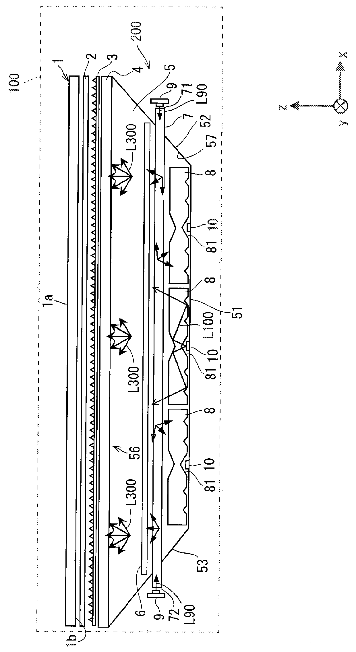
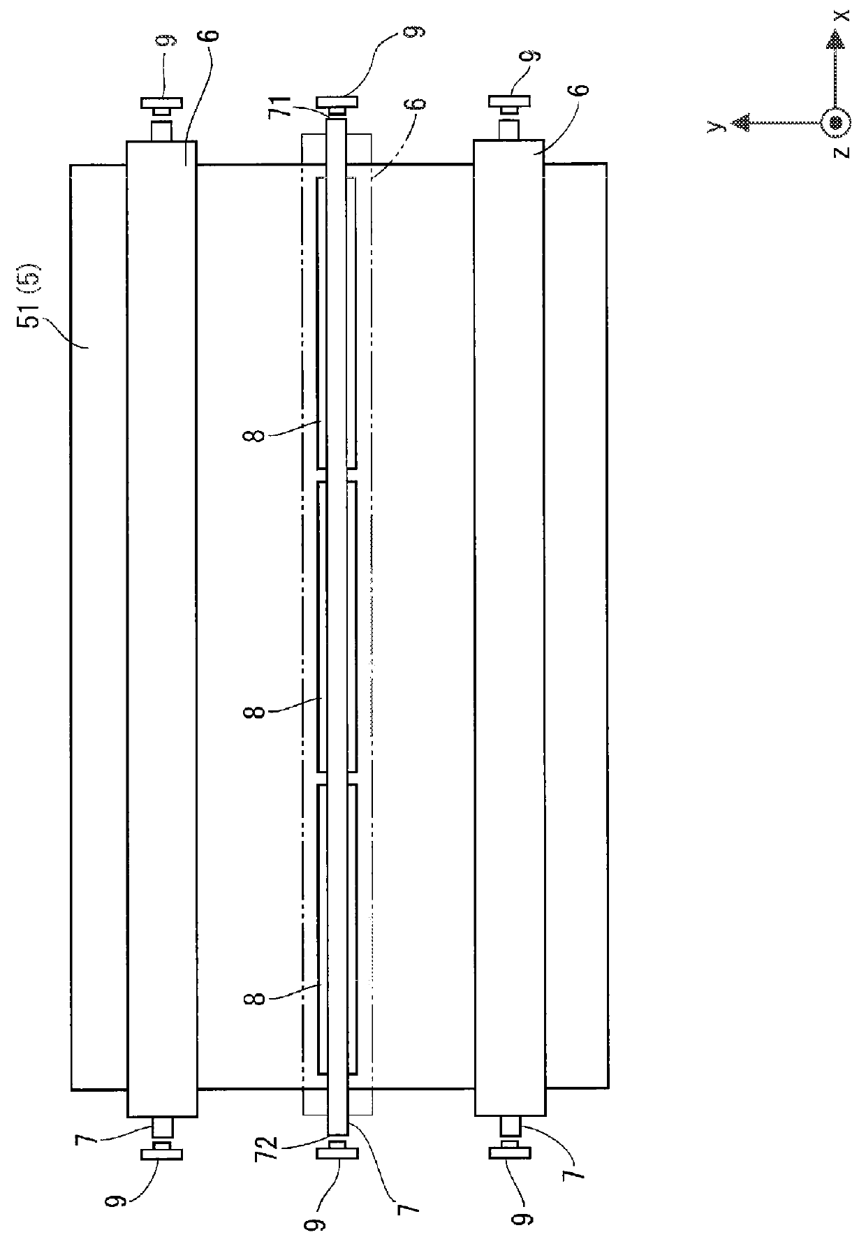
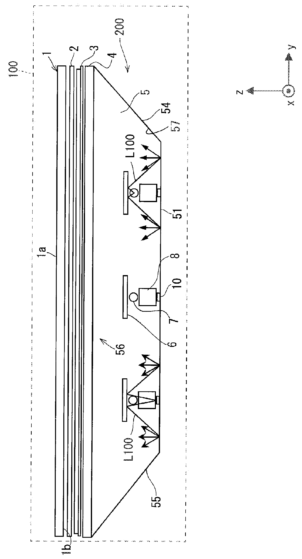
[0033]A preferred embodiment according to the present invention will be described below with reference to the drawings. FIG. 1 is a view schematically showing an example of a structure of a liquid crystal display device 100 according to the preferred embodiment, FIG. 2 is a view schematically showing an example of a structure of a surface light source device 200, and FIG. 3 is a view schematically showing an example of the structure of the liquid crystal display device 100.

[0034]As shown in FIG. 1, the liquid crystal display device 100 includes a transmission type liquid crystal panel 1 formed of a liquid crystal display element, an optical sheet 2, an optical sheet 3, and the surface light source device 200. Moreover, although not illustrated in FIG. 1, the liquid crystal display device 100 further includes a control unit 31, a liquid crystal panel driving unit 32, an LED light source driving unit 33a, and a laser beam source driving unit 33b as shown in FIG. 7....


PUM


Abstract

A surface light source device includes a laser beam source, a laser beam guide rod for converting a laser beam into first linear light, an LED light source, an LED light guide rod for converting LED light into second linear light, a reflecting bar having a reflecting region for reflecting part of the first linear light and the second linear light and a transmitting region for transmitting a residual part of the first linear light and the second linear light, and a light reflecting portion formed in a box shape and having an opening portion with an emission side opened and a reflecting surface on an inside of the box shape. In the first linear light and the second linear light, part thereof is reflected by the reflecting region and the reflecting surface and a residual part is transmitted through the transmitting region and is emitted from the opening portion.

Description

BACKGROUND OF THE INVENTION[0001]1. Field of the Invention[0002]The present invention relates to a surface light source device for illuminating a back surface of a liquid crystal display element by two types of light sources having different characteristics, thereby displaying an image on the liquid crystal display element, and a liquid crystal display device including the surface light source device.[0003]2. Description of the Background Art[0004]A liquid crystal display element provided in a liquid crystal display device does not emit light by itself. For this reason, the liquid crystal display device includes a backlight device (a surface light source device) as a light source for illuminating the liquid crystal display element at a back surface side of the liquid crystal display element.[0005]Moreover, the liquid crystal display element includes a color filter and transmits, through a color filter, only light having a part of wavelengths in light emitted from a fluorescent lamp ...

Claims


Application Information

Patent Timeline
IPC IPC(8): F21V8/00G02F1/1335
CPCG02B6/0031G02B6/0076G02F1/133603G02F1/133524G02F1/133605G02B6/0066F21S8/00F21V13/02F21V19/001G02F1/133615G02B6/0021G02B6/0053G02B6/0068G02F1/133607G02F1/133624G02F1/133626
Inventor OKIMOTO, NAMINIIKURA, EIJISAWANAKA, TOMOHIKOYAMAMOTO, TAKESHI
Owner MITSUBISHI ELECTRIC CORP
Why Eureka
Try Eureka