Light source device and projector

a light source device and projector technology, applied in fixed installations, lighting and heating apparatus, instruments, etc., can solve the problems of reducing the efficiency of light, affecting the observer, and causing high-frequency noise in the illumination light generated by the diffracting optical element, so as to reduce the speckle noise and improve the light efficiency

Active Publication Date: 2009-07-02
SEIKO EPSON CORP
View PDF5 Cites 88 Cited by
  • Summary
  • Abstract
  • Description
  • Claims
  • Application Information

AI Technical Summary

Benefits of technology

[0012]The invention has an advantage of providing a light source device and a projector achieving the even intensity distribution, and capable of reducing the speckle noise while improving the light efficiency.

Problems solved by technology

The scintillation causes the observer to have a dazzling feeling, and becomes a cause of exerting an adverse influence on the observer such as an uncomfortable feeling when appreciating images.
Specifically, in the display described in the Document 1, since the diffusion plate diffuses the light, efficiency of the light problematically drops.
Further, in the illumination device described in the Document 2, although the diffracting optical element generates the illumination light for illuminating the predetermined illumination area, there are some cases in which high-frequency noise is caused in the illumination light generated by the diffracting optical element.
In such cases, it is difficult for the diffracting optical element to generate the illumination light with an even intensity distribution.

Method used


Image

  • Light source device and projector
  • Light source device and projector
  • Light source device and projector

Examples


first embodiment

[0045]The light source device according to a first embodiment of the invention will be explained with reference to FIGS. 1 through 5.

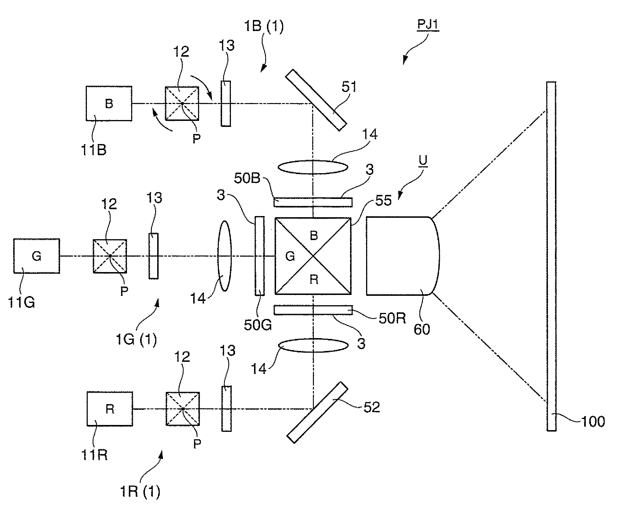
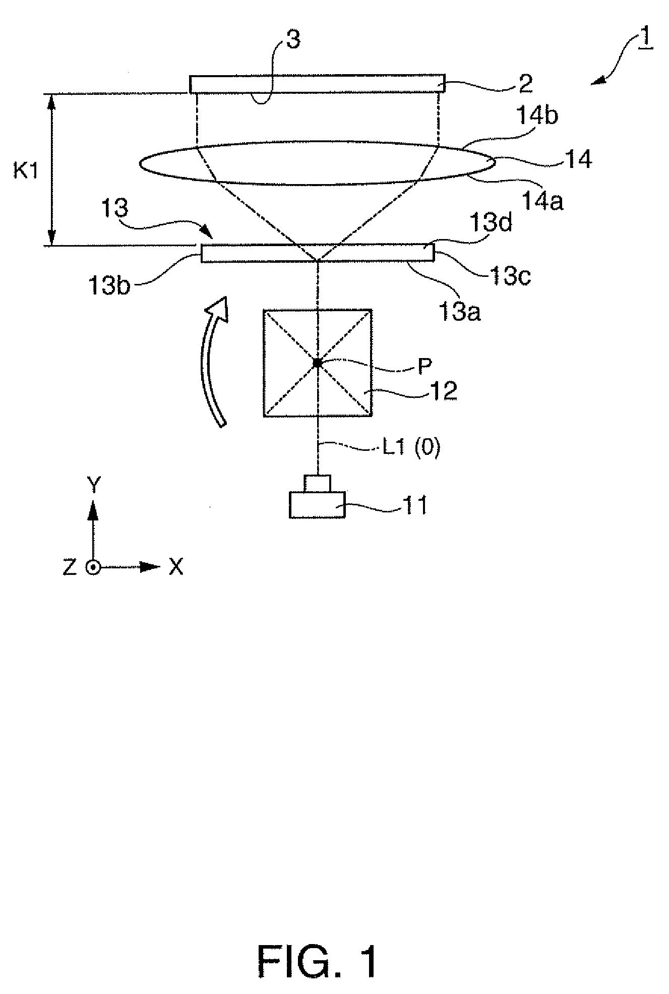
[0046]As shown in FIG. 1, a light source device 1 is for illuminating a illumination (illuminated) surface 3 of an illumination target 2, and is provided with a laser source (a light source) 11 for emitting a laser beam, a rod member (a light path conversion member) 12, a holographic optical element 13, and a refractor 14.

[0047]It is assumed that the center axis of the light beam emitted from the laser source 11 is a Y-axis, an axis directed from a left end 13b of the holographic optical element 13 described later to a right end 13c thereof is an X-axis, and an axis directed from a lower end 13e of the holographic optical element 13 to an upper end 13d thereof is a Z-axis.

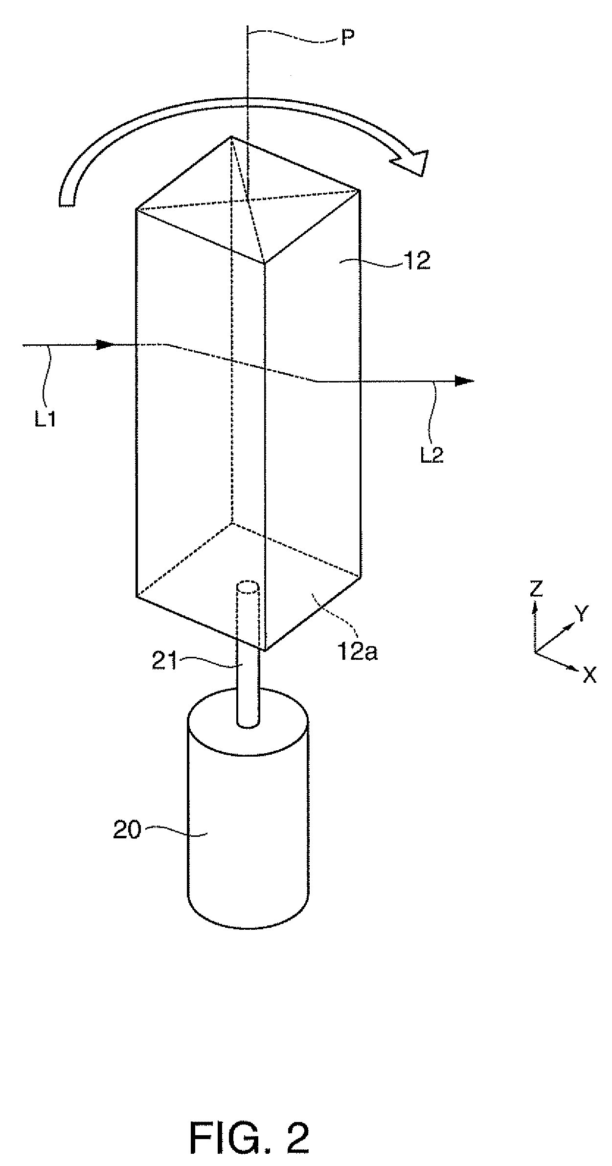
[0048]The rod member 12 is a regular quadrangular prism made of a glass material. The rod member 12 is disposed on the light path between the laser source 11 and the holographic optic...

second embodiment

[0075]A second embodiment according to the invention will now be explained with reference to FIGS. 6A and 6B. It should be noted that in the drawing of each of the embodiments described hereinafter, portions with configurations common to the light source device 1 according to the first embodiment described above will be denoted with the same reference numerals, and the explanations therefor will be omitted.

[0076]The light source device according to the present embodiment is different from that of the first embodiment in that the entrance range of the laser beam input from the side surface 12b of the rod member 12 is regulated. The other configurations are the same as those of the first embodiment.

[0077]There are caused some cases in which the incident beam L1 and the output beam L2 are not parallel to each other depending on the position of the rod member 12 where the laser beam emitted from the laser source 11 is input.

[0078]Firstly, as shown in FIG. 6A, in the case in which the ro...

third embodiment

[0089]A third embodiment according to the invention will now be explained with reference to FIGS. 7A, 73, and 8.

[0090]In the present embodiment, the case in which the holographic element 13 is disposed so that the imaging surface of the reproduction image by the holographic optical element 13 becomes the illumination surface 3 of the illumination target 2 as described in the first embodiment will be explained.

[0091]The cross-sectional diagram of the intensity distribution in the illumination surface 3 of the illumination target 2 has the luminance spikes composed of a large number of high-frequency components as shown in FIG. 7A.

[0092]In contrast, in the case in which the imaging surface of the reproduction image by the holographic optical element 13 is different from the illumination surface 3 of the illumination target 2, namely, as shown in FIG. 8, the distance K2 between the holographic optical element 13 and the illumination target 2 is different from the distance K1 between th...


PUM


Abstract

A light source device adapted to generate an illumination light beam for illuminating an illuminated surface includes a light source adapted to emit a light beam, a light path conversion member adapted to rotate around an axis perpendicular to a center axis of the light beam emitted from the light source to convert a light path of the light beam emitted from the light source, an overlapping illumination element adapted to overlap a light beam emitted from the light path conversion member on the illuminated surface, the overlapping illumination element having an entrance position of the light bream input to the overlapping illumination element varies with time, and a rotating section adapted to rotate the light path conversion member.

Description

BACKGROUND[0001]1. Technical Field[0002]The present invention relates to a light source device and a projector.[0003]2. Related Art[0004]In recent years, while demands for downsizing of projectors are growing, in accordance with increase in output power of semiconductor lasers and appearance of blue semiconductor lasers, projectors using laser sources have been developed. The projectors of this kind are capable of having a sufficiently large color reproduction range because the wavelength band of the light source is narrow, and also capable of downsizing and reducing the number of components, and consequently, have a great potential as display devices of the next generation.[0005]However, in the projectors using the laser sources, there are some cases in which a phenomenon so called “scintillation (or “speckle”)” is caused, when performing display with image light. In the scintillation, interference of light is caused on scatterer such as a screen, which distributes bright points an...

Claims


Application Information

Patent Timeline
Patent Type & Authority Applications(United States)
IPC IPC(8): F21V33/00F21Y101/00
CPCG02B26/0883G03B21/208G03B21/2033G02B27/48G03H1/32G03H2001/2292
Inventor YAMAUCHI, TAISUKETAKEDA, TAKASHITAKAGI, MASAYUKI
Owner SEIKO EPSON CORP
Why Eureka
Try Eureka