
Containment structure

a technology of containment structure and container, applied in the field of containment structure, can solve the problems of significant surface area receipt, achieve the effects of enhancing textile layer strength, high shear resistance and high degree of movement to the containment structur

Inactive Publication Date: 2009-07-02
WTB GRP LTD +1
View PDF6 Cites 17 Cited by
  • Summary
  • Abstract
  • Description
  • Claims
  • Application Information

AI Technical Summary

Benefits of technology

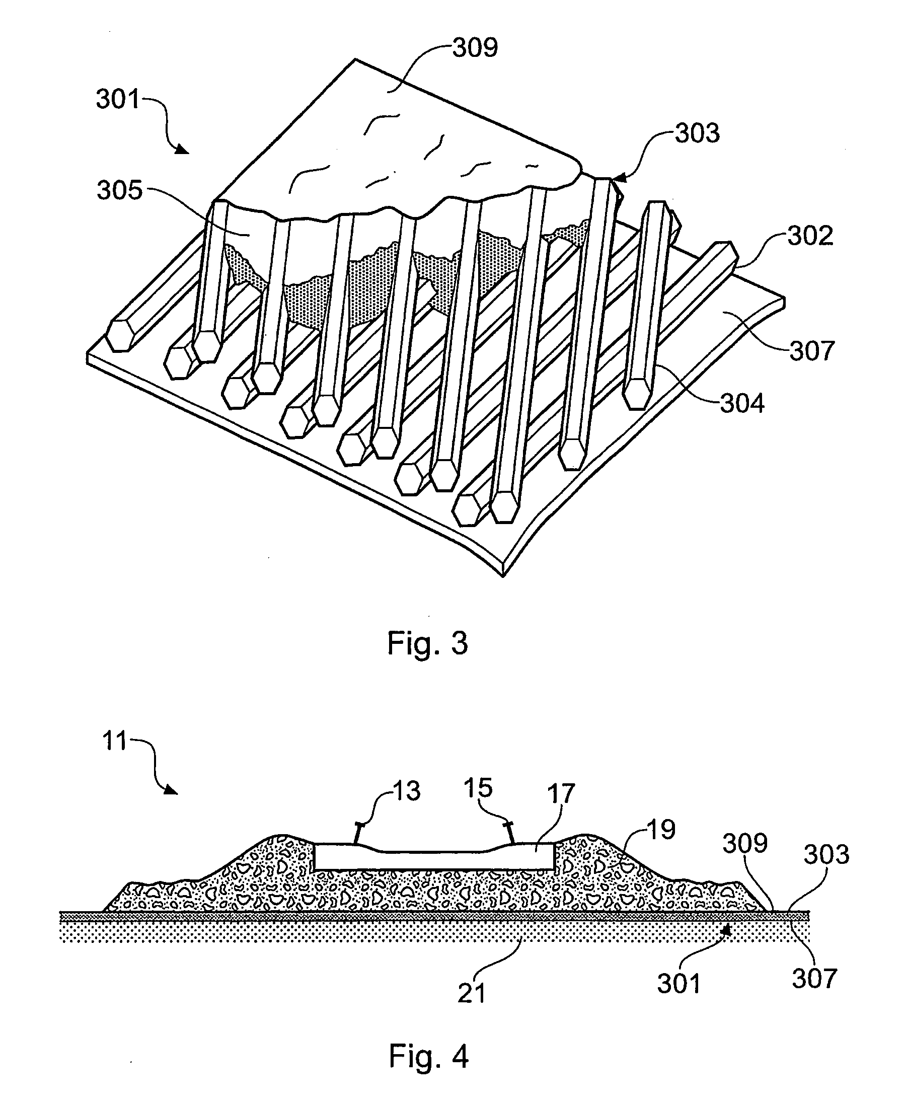
[0011]The particulate material containment structure may be flexible. Preferably the support matrix is flexible. Such flexible properties may allow the containment structure to be supplied in a roll form, thus enabling the particles to be easily transported and uniformly distributed or positioned. The containment structure could substantially retain the physical characteristics of an equivalent thickness of the original particulate material.
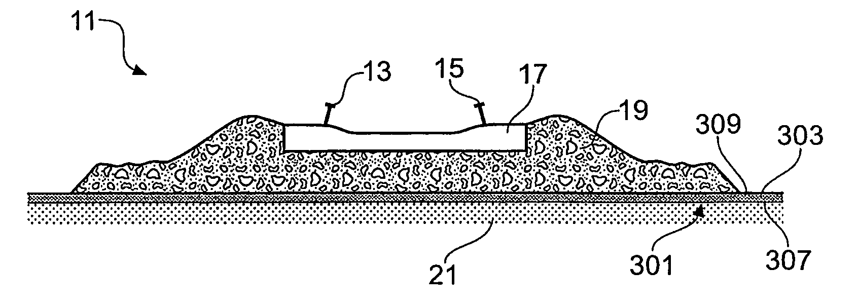
[0050]The present invention also comprehends a building composite, comprising a containment structure as described hereinbefore, the composite being suitable for use in the construction of a landfill cell, or the like, having substantially upright walls. By lining the interior surface of a landfill cell, or the like, it may be possible to increase the angle between the base and wall of a conventional landfill cell thereby increasing its capacity. By increasing the capacity of a landfill cell and allowing the walls to be substantially upright, the ground in a landfill area may be utilized more efficiently. The embankment angle or wall angle of a landfill cell, for example, may be increased due to the high coefficient of friction that the present invention generates when contacting another surface. The present invention may, in this application, act to retain the shape of the landfill cell, or the like, wall. The landfill cell, or the like, wall may otherwise collapse or cave-in when the angle between the base and wall is increased to a value which may be accommodated by the present invention. The present invention may therefore provide a support to the substantially upright walls.

Problems solved by technology

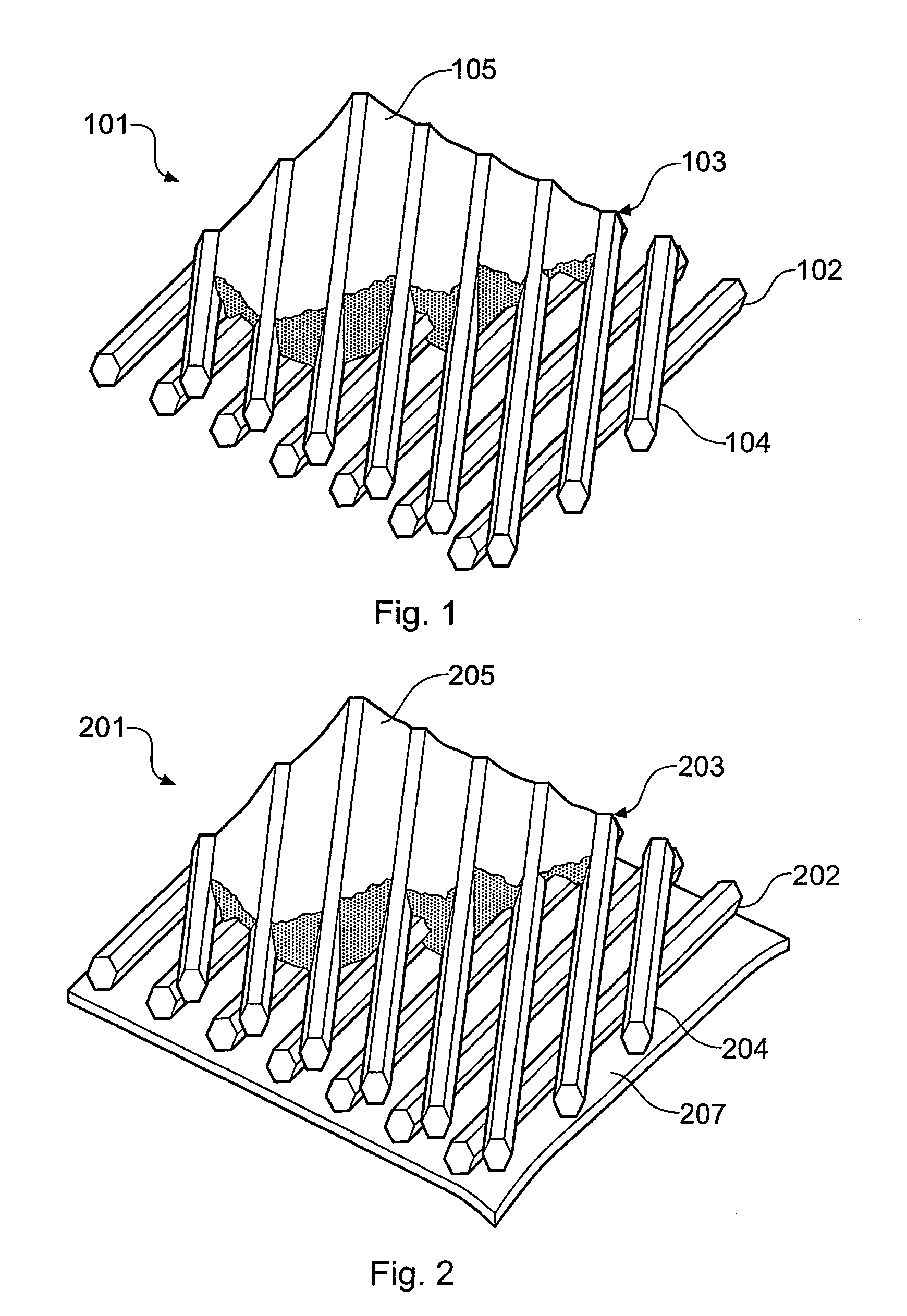
The support matrix may therefore shrink significantly whilst curing, causing it to recede from significant portions of the surface area of individual particles within the structure.

Method used


Image

  • Containment structure
  • Containment structure
  • Containment structure

Examples


Embodiment Construction

[0073]In the following description, numerous specific details are set forth in order to provide a more thorough description of the present invention. It will be apparent, however, to one skilled in the art, that the present invention may be practiced without these specific details. In other instances, well-known features have not been described in detail so as not to obscure the invention.

[0074]At present the problem of pumping erosion is resolved by the application of a 100 mm thick bed of appropriately graded sand installed at the interface of the stone ballast and the clay / silt base layers. Sand is used because of its natural ability to filter clay and silt type soils through natural bridging. Further, the sand barrier allows water to drain freely from the clay surface whilst controlling the upward migration of clay particles.

[0075]Recent studies have shown, however, that the actual level of migration of clay particles into this type of sand barrier is minimal. For example, the e...


PUM

PropertyMeasurementUnit
mean mass aerodynamic diameteraaaaaaaaaa
bend radiusaaaaaaaaaa
thickaaaaaaaaaa

Abstract

A particulate material containment structure and a method of manufacturing such a structure are provided herein. The structure may comprise an open-cell matrix and an intermediary composite comprising particulate material retained in a support matrix, wherein the intermediary composite is retained within the open-cell matrix. In various embodiments, the structure may comprise at least one textile layer, such as a geotextile layer. The present invention has particular application in preventing the phenomenon known as pumping erosion.

Description

CROSS-REFERENCE TO RELATED APPLICATIONS[0001]This application claims priority to PCT Application No. PCT / GB / 2007 / 002502 titled Containment Structure, filed Jul. 3, 2007, which claims priority to Great Britain Application No. 0614132.9, filed Jul. 15, 2006.BACKGROUND OF THE INVENTION[0002]1. Field of the Invention[0003]The present invention relates to a containment structure, and in particular the invention relates to a particulate material containment structure, a method of manufacturing such a structure and uses of such a structure.[0004]2. Related Art[0005]Pumping erosion is the result of train axle loads rippling along a railway track. The rapid sequential loading and unloading of rail sleepers caused by a moving train transmits a pulsating load to the ballast / sub-base interface. Accordingly, where a track is built on a fine clay / silt sub-base, this pulsating load may cause the surface of the clay / silt to liquefy when wet, and may subsequently be forced upwards into the ballast l...

Claims


Application Information

Patent Timeline
Patent Type & Authority Applications(United States)
IPC IPC(8): E02D31/00E04B1/00B32B37/00G06K19/00
CPCE01B1/001Y10T156/10E02D31/004E01B2204/05E01B2/006E02D27/32
Inventor SHARLEY, PAULTHOMAS, BASIL
Owner WTB GRP LTD
Learn More