
Stator cascade of turbo type fluid machine

Active Publication Date: 2009-07-02
IHI CORP
View PDF8 Cites 16 Cited by
  • Summary
  • Abstract
  • Description
  • Claims
  • Application Information

AI Technical Summary

Benefits of technology

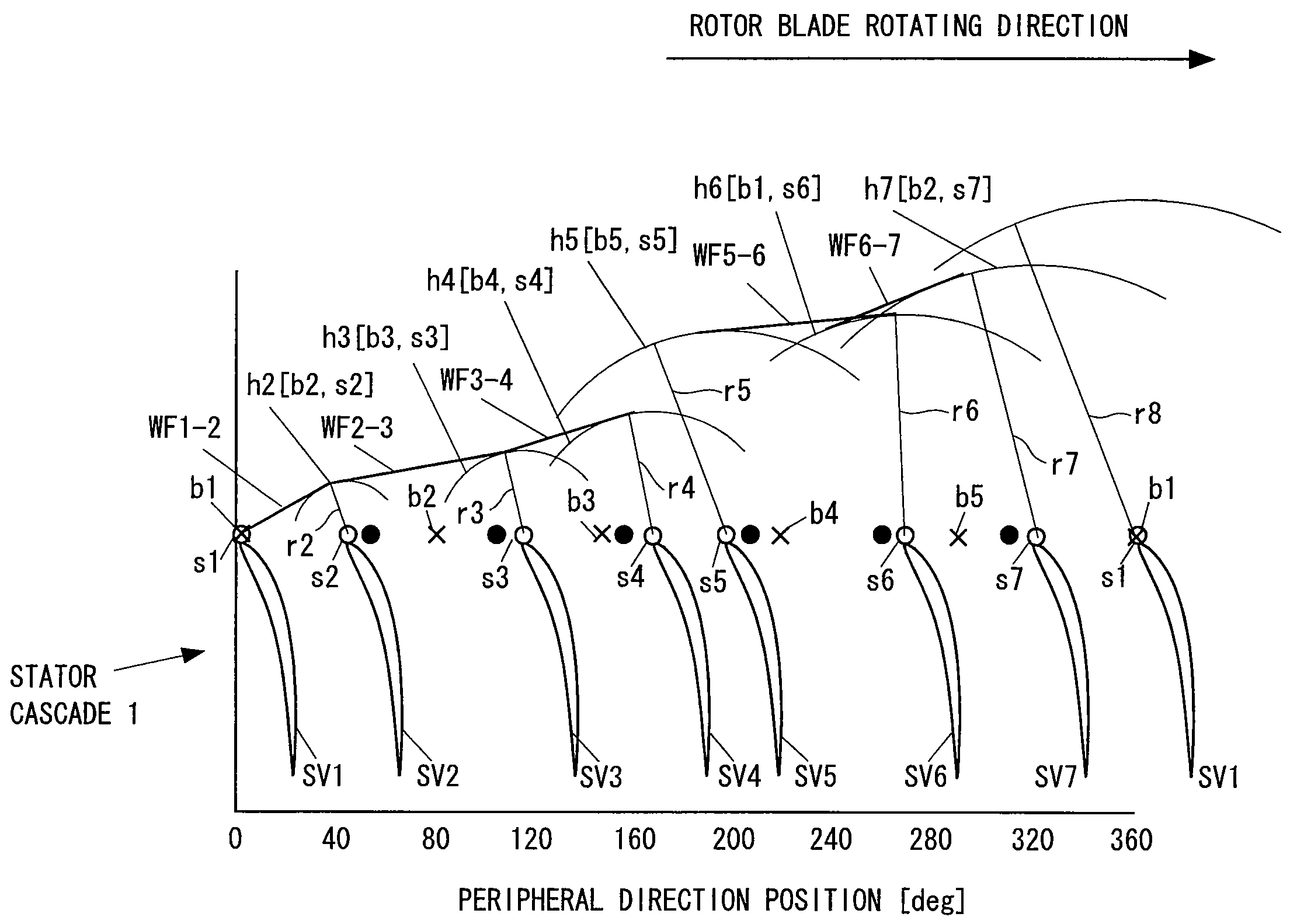
[0019]The present invention is made by taking the matters mentioned above into consideration, and an object of the present invention is to provide a stator cascade of a turbo type fluid machine which can reduce an interference noise without enlarging a rotor stator blade interval as well as reducing a used amount of a sound absorption material.

Problems solved by technology

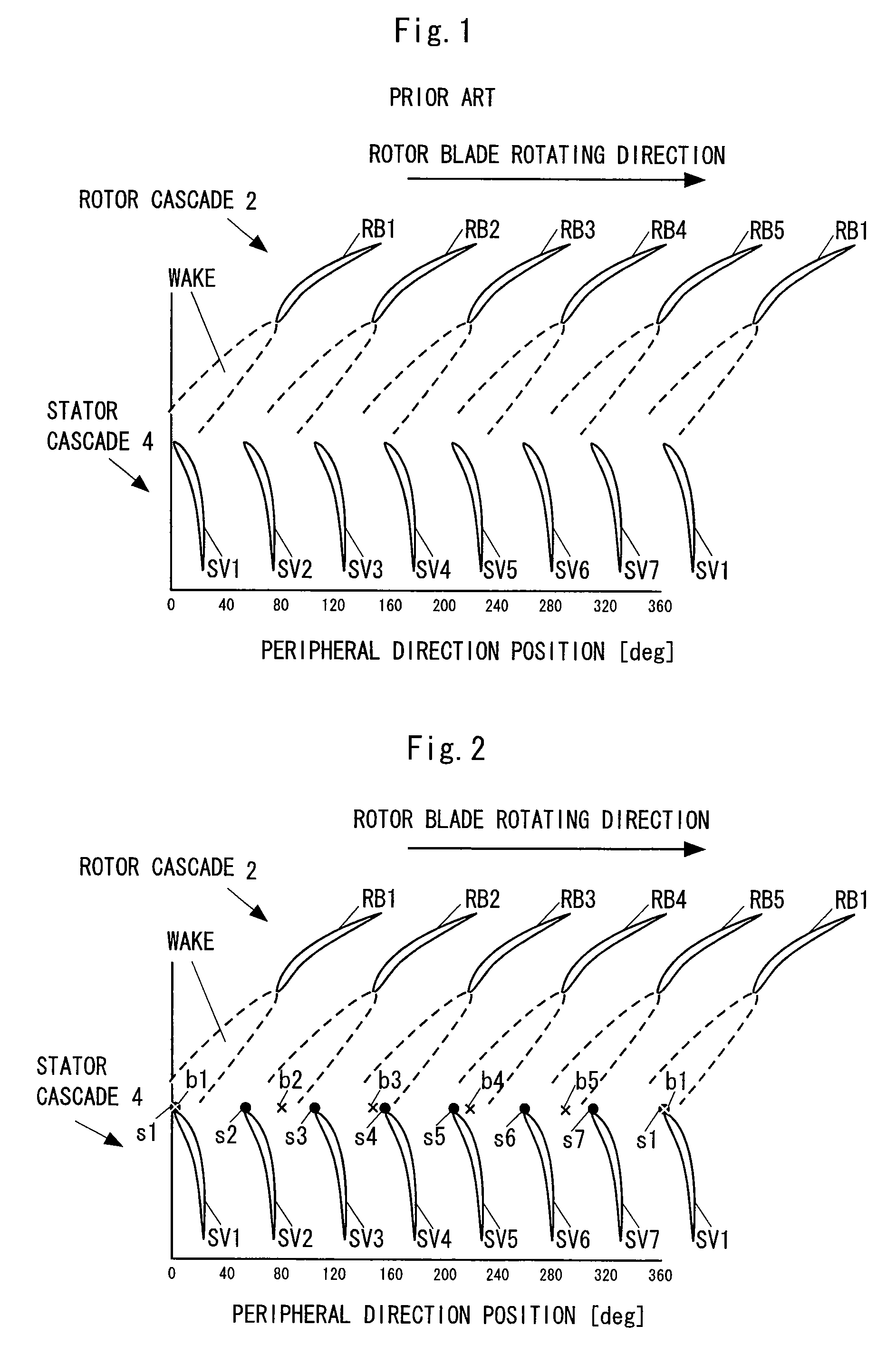
Further, since the wake is moved in the peripheral direction together with the rotor blade, a periodical interference is repeated between the wake and each of the stator blades SV1 to SV7, and a great pressure fluctuation is generated on a surface of the stator blade due to the interference.
Accordingly, in the light of an environmental suitability, it comes to an important problem to reduce the interference noise generated in the fan, particularly in the turbofan engine.
However, this method only cuts off the primary component of the noise, and can not cut off the higher order component equal to or more than the secondary component.
However, the following problems are generated in these countermeasures.
However, for example, in the case of the jet engine, since the sound absorbing plate is required at about 70 kg for reducing the noise at 3 dB from an actual condition, there is generated a problem that an increase of a cost and an engine weight is caused.
However, for example, in the case of the fan of the jet engine, if the interval in an engine axial direction between the fan rotor blade and the fan stator blade is enlarged, the length in the engine axial direction is elongated, so that there is generated a problem that an increase of the engine weight is caused.

Method used


Image

  • Stator cascade of turbo type fluid machine
  • Stator cascade of turbo type fluid machine
  • Stator cascade of turbo type fluid machine

Examples


embodiment

[0120]With regard to the stator cascade of the turbo type fluid machine in accordance with the present invention, there is executed an analysis for comprehending the effect. In this analysis, one end of a double cylinder duct formed by simulating a fan duct is set as a leading edge position of the stator blade, as shown in FIG. 8, a sound source distribution formed by simulating thirty stator blades serving as the sound source as shown in FIG. 9 is applied to the leading edge position of the stator blade, and there is searched how many modes the mode distributions in the other end of the duct are dispersed. In this case, a flow having a fixed axial flow Mach number is applied to an inverse direction to the moving direction of the sound wave within the duct.

[0121]In this analysis, in accordance that the mode distributions in the other end of the duct are divided into a lot of modes, and the magnitude thereof is smaller in comparison with the sound source applied to one end side, the ...


PUM


Abstract

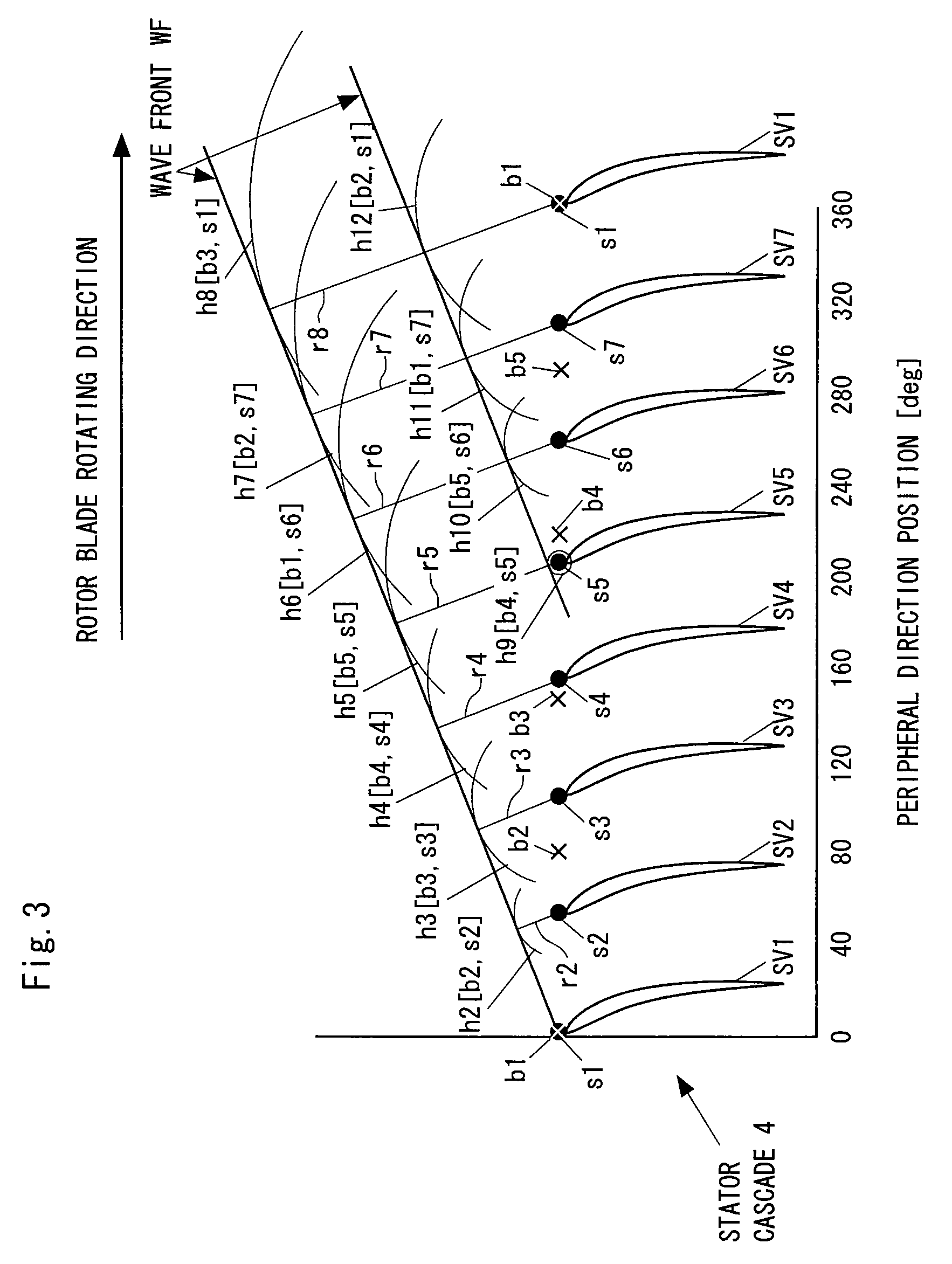
In the invention, stator blades are arranged in such a manner that respective intervals between the adjacent stator blades (SV) become unequal at least partly. If the stator blades are arranged as mentioned above, there are formed wave fronts having different moving directions and phases, and these wave fronts are interfered with each other so as to be attenuated. Accordingly, an interference noise is reduced. Therefore, in accordance with the invention, it is possible to reduce an interference noise without enlarging a rotor stator blade interval as well as reducing a used amount of a sound absorption material.

Description

BACKGROUND OF THE INVENTION[0001]1. Technical Field of the Invention[0002]The present invention relates to a stator cascade of a turbo type fluid machine such as a fan, a compressor, a turbine or the like.[0003]2. Description of the Related Art[0004]FIG. 1 is a view schematically showing a layout state of conventional rotor cascade 2 and stator cascade 4, for example, in a turbo type fluid machine such as a fan, a compressor, a turbine or the like of a jet engine.[0005]In this drawing, a vertical direction corresponds to an axial direction and a horizontal direction corresponds to a peripheral direction. As shown in this drawing, the rotor cascade 2 is constituted by a plurality of rotor blades RB1 to RB5 which are arranged at an equal interval in a peripheral direction, whirls in a direction shown by an arrow in the drawing, and feeds a fluid such as an air or the like to a downstream side. The stator cascade 4 is arranged in a downstream side of the rotor cascade 2, is constituted...

Claims


Application Information

Patent Timeline
IPC IPC(8): F01D9/04
CPCF01D5/141F01D5/142F01D5/26F01D9/041F05D2260/96F04D29/666F05D2260/961Y02T50/671Y02T50/673F04D29/542F04D29/544Y02T50/60
Inventor TSUCHIYA, NAOKIIDETA, TAKEOMI
Owner IHI CORP
Learn More