Rotor Compressor

a rotor compressor and compressor technology, applied in the direction of machines/engines, rotary/oscillating piston pump components, liquid fuel engines, etc., can solve the problems of reducing the reliability of mechanical structure and sealing, complex process, and inability to guarantee sealing, etc., to achieve excellent manufacturability, simple structure, and increased volume efficiency of rotor compressors

Active Publication Date: 2009-07-02
YUN XIAOYING
View PDF8 Cites 30 Cited by
  • Summary
  • Abstract
  • Description
  • Claims
  • Application Information

AI Technical Summary

Benefits of technology

[0024]With the separating means of the invention, the volume efficiency of the rotor compressor is increased greatly, and the rotor compressor has a simple structure and an excellent manufacturability, and achieves rational conditions for mechanical movement, the noise and vibration can be further reduced.

Problems solved by technology

Conventional rotor compressors have significant advantages compared to other types of compressors, but they have the following drawbacks: the manufacturing process is complicated, the sealing is not reliable, and the reliability of the mechanical structure and the sealing drops significantly especially when the volume increases, and as a result, it is difficult to increase flow volume.
The main reason that results in the above drawbacks lies in that the movable separating block, which separates the high pressure chamber from the low pressure chamber, has a small moving range and has a poor reliability.
And when increasing the flow volume, the manufacturing process is more difficult to realize.

Method used


Image

  • Rotor Compressor
  • Rotor Compressor
  • Rotor Compressor

Examples


second embodiment

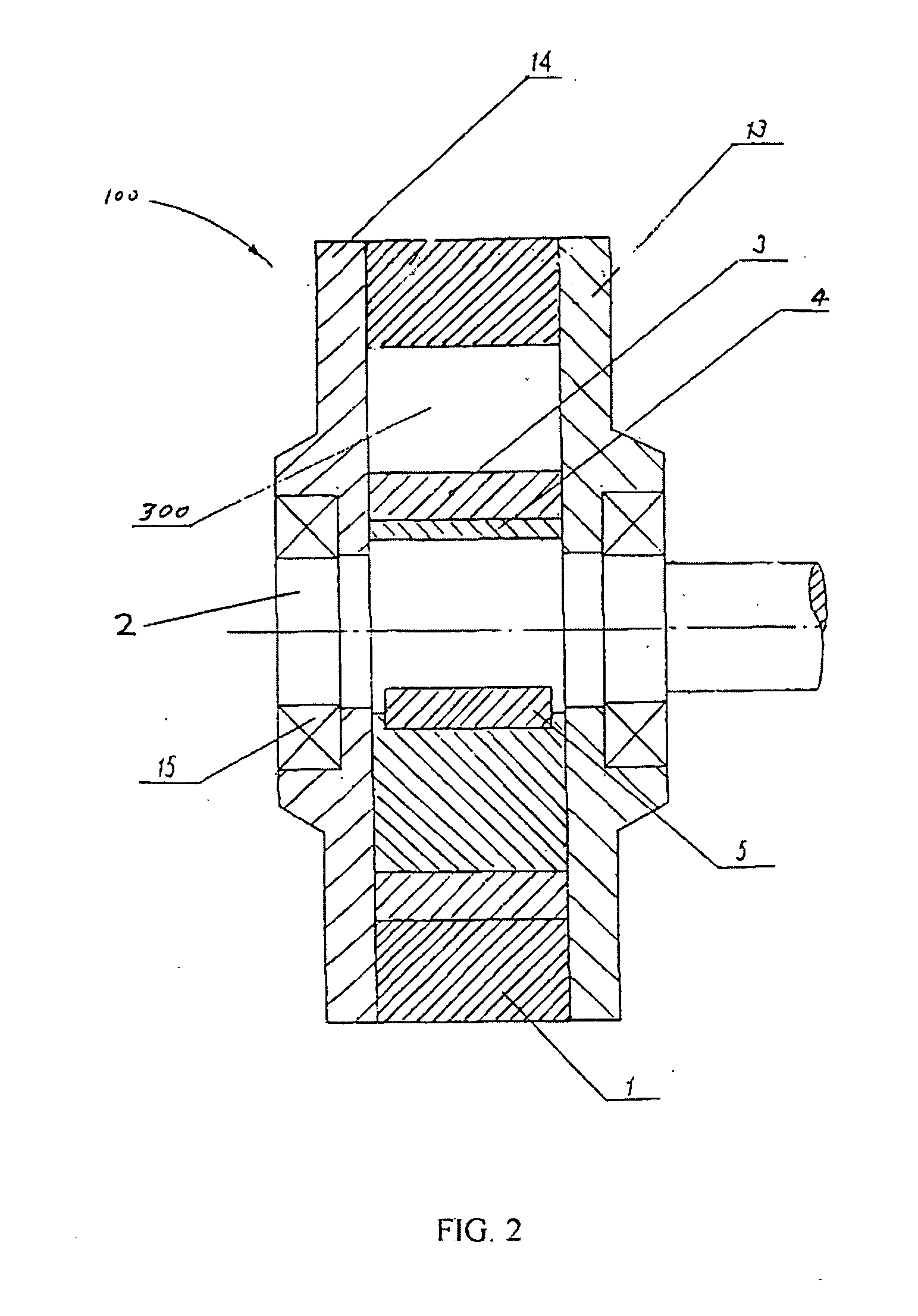
[0054]As shown in FIG. 6, in the invention, the contact member 7′ with a cylindrical surface is fixedly attached to the bush 3 of the eccentric rotor assembly 200, and a side of the separator plate 8, which faces the bush 3, is formed with a circular arc slot 15′ which extends axially, and the radius of the cylindrical surface of the contact member 7′ is substantially equal to or slightly smaller than the radius of the circular arc slot 15′. In an assembled state, the cylindrical surface of the contact member 7′ is positioned in the circular arc slot 15′ formed on the separator plate 8, and a sealing contact is established therebetween to separate the sealed chamber 300 into the induction chamber 70 and the exhaustion chamber 71.

[0055]Similar to the first embodiment (refer to FIGS. 3-5), the contact member 7′, which is fixedly attached to the bush 3, and the separator plate 8 are connected through the connecting member 6. The contact member 7′ is formed with a central hole at each o...

first embodiment

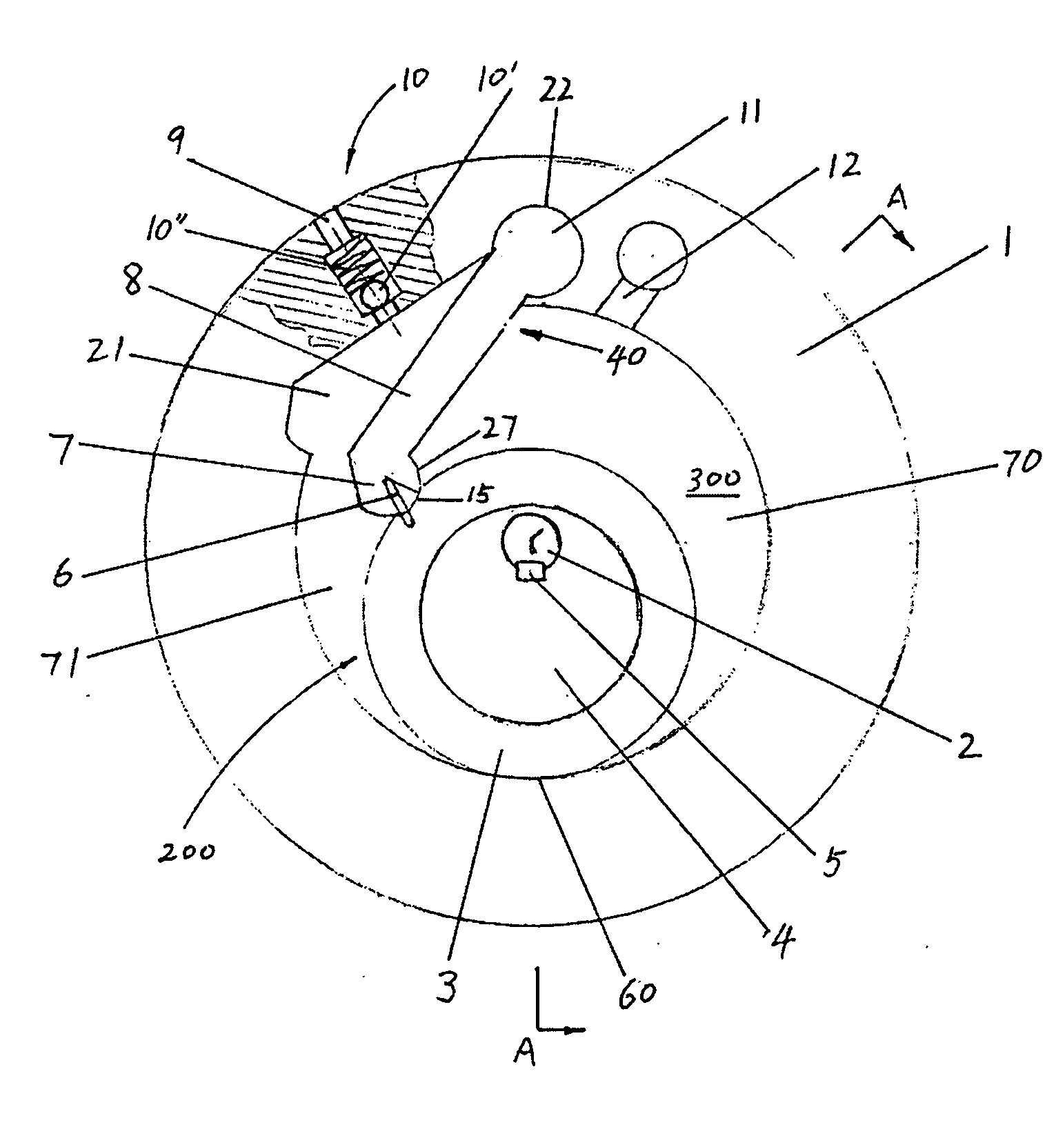
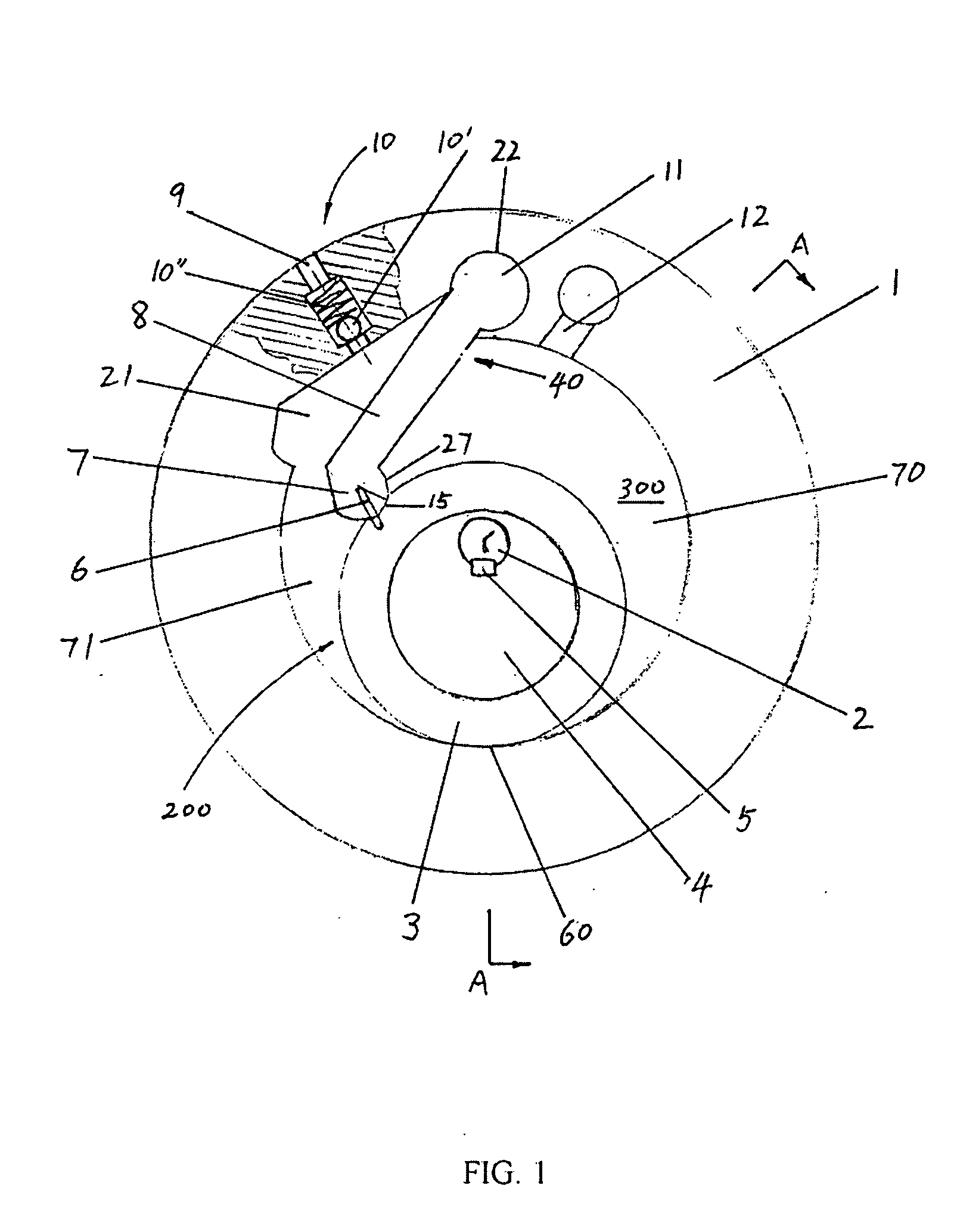
[0060]In the first embodiment described above, the separator plate 8, the pivot shaft 11 and the contact member 7 are integrally formed. However, the separator plate 8, the pivot shaft 11 and the contact member 7 can also be separate members, and are fixedly attached to one another to form the separating means 40.

[0061]In the embodiments described above, the invention is described and illustrated as a rotor compressor with one cylinder. However, one skilled in the art will recognize that the invention is also applicable to a rotor compressor with more than one cylinder. Where a plurality of cylinders are applied, the cylinders may be arranged in the axial direction. The phase angle between the rotors in the cylinder blocks may be equal to 360 degrees / n, where n is the number of the cylinders.


PUM


Abstract

A rotary piston compressor comprises a cylinder block (100), an eccentric rotor group (200) being fitted in the chamber of the cylinder block, a shaft (2) and a separating means (40). The eccentric rotor group (200) comprises a cylindrical rotor (4) provided on the shaft (2) and rotatable therewith, and a collar (3) rotationally provided on the cylindrical rotor (4). The separating means (40) is used for separating the axially extended sealed chamber, which is formed between the outer peripheral surface of the eccentric rotor group (200) and the inner wall of the cylinder block (100), into an induction chamber (70) and an exhaustion chamber (71). Wherein, the separating means (40) comprises: a baffle (8) provided between the inner wall of the cylinder block (100) and the collar (3) provided on the outer periphery of the eccentric rotor (4), a contact member (7) provided between the baffle (8) and the collar (3) and contacted therewith, and a jointing element (6) connecting the contact member (7) to the baffle (8) and the collar (3) respectively.

Description

FIELD OF THE INVENTION[0001]The invention relates to an energy conversion device which converts mechanical energy into pressure energy, and particularly to a rotor compressor.BACKGROUND OF THE INVENTION[0002]Conventional rotor compressors have significant advantages compared to other types of compressors, but they have the following drawbacks: the manufacturing process is complicated, the sealing is not reliable, and the reliability of the mechanical structure and the sealing drops significantly especially when the volume increases, and as a result, it is difficult to increase flow volume. The main reason that results in the above drawbacks lies in that the movable separating block, which separates the high pressure chamber from the low pressure chamber, has a small moving range and has a poor reliability. And when increasing the flow volume, the manufacturing process is more difficult to realize.SUMMARY OF THE INVENTION[0003]In consideration of the above, an object of the invention...

Claims


Application Information

Patent Timeline
Patent Type & Authority Applications(United States)
IPC IPC(8): F01C19/00
CPCF01C1/39F01C21/0809
Inventor YUN, XIAOYING
Owner YUN XIAOYING
Why Eureka
Try Eureka