Rotor Assembly System and Method

a technology of rotors and assemblies, applied in the direction of liquid fuel engines, adaptive control, instruments, etc., can solve the problems of vibration, increased complexity of engine design, and difficulty in reducing undesirable eccentricity, subject to non-perpendicularity or tilt of the flange,

Inactive Publication Date: 2009-07-02
GENERAL ELECTRIC CO
View PDF16 Cites 16 Cited by
  • Summary
  • Abstract
  • Description
  • Claims
  • Application Information

AI Technical Summary

Problems solved by technology

Vibration may occur due to mass unbalance around an axial centerline axis of the engine, and / or due to eccentricity of the rotor therearound.
Runout, roundness, concentricity and flatness are of particular concern in an assembly of rotor components since they may contribute to eccentricity.
The individual rotors in a typical gas turbine engine vary in configuration for aerodynamic, mechanical, and aeromechanical reasons, which increases the complexity of the engine design and the difficulty in reducing undesirable eccentricity.
Each rotor is separately manufactured and is subject to eccentricity between its forward and aft mounting flanges, and is also subject to non-perpendicularity or tilt of its flanges relative to the axial centerline axis of the engine.
Both eccentricity and tilt of the rotor end flanges are random and typically limited to relatively small values.
However, the assembly of the individual rotors with their corresponding flange eccentricities and tilts are subject to stack-up and the possibility of significantly larger maximum eccentricity due to the contribution of the individual eccentricities.
These methods may ignore other opportunities for an optimal assembly.
Using the same example with two peaks, if the mating part had a similar feature (two peaks), the computer does not optimize the stack by looking at an interlocking of peaks.

Method used


Image

  • Rotor Assembly System and Method
  • Rotor Assembly System and Method
  • Rotor Assembly System and Method

Examples


Embodiment Construction

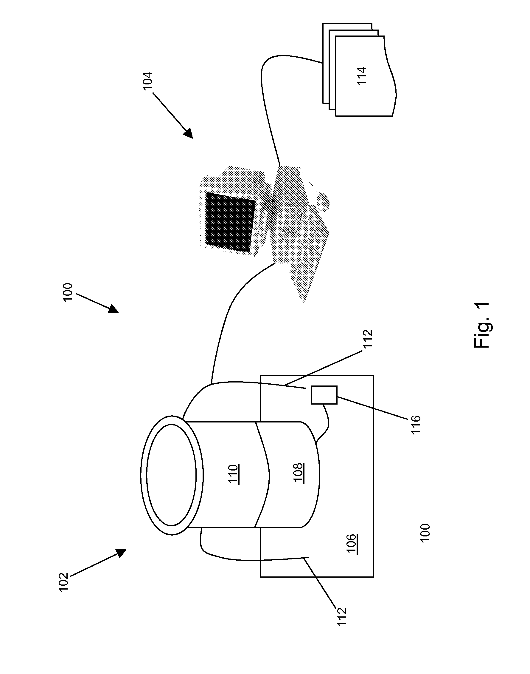
[0012]It should be understood that any reference to an electronic connection between components in the following description could be a wired or wireless connection. FIG. 1 illustrates schematically one exemplary embodiment of a system 100 for assembling a rotor stack. The system 100 includes a measurement system 102 and a computer 104 connected to the measurement system 102. The measurement system 102 may be used to measure one or more characteristics of a plurality of rotor disks that may be used to assemble a rotor stack. The one or more characteristics may be any characteristic of a rotor disk that, taken separately or combined as a rotor stack, may contribute to the eccentricity of the rotor stack. For example, the characteristics may include runout, roundness, concentricity, perpendicularity, parallelism and / or flatness. The measurement system may include a platform 106 that supports a turntable 108. The turntable 108 may fix the rotor disk 110 in a rotatable relationship to t...


PUM


Abstract

A system for assembling a rotor stack having a plurality of rotor disks may include a measurement system for measuring characteristics of the rotor disks, a computer electronically connected to the measurement system for capturing data from the measurement system, and solid modeling software for creating a virtual stack of the rotor disks optimized for concentricity.

Description

BACKGROUND OF THE INVENTION[0001]The exemplary embodiments relate generally to rotor assemblies for gas turbine engines and more particularly to methods and systems for assembling rotor assemblies.[0002]A gas turbine engine is an example of a large rotary machine requiring dimensional precision for reducing vibration at high rotational speed. Vibration may occur due to mass unbalance around an axial centerline axis of the engine, and / or due to eccentricity of the rotor therearound. Runout, roundness, concentricity and flatness are of particular concern in an assembly of rotor components since they may contribute to eccentricity. The individual rotors in a typical gas turbine engine vary in configuration for aerodynamic, mechanical, and aeromechanical reasons, which increases the complexity of the engine design and the difficulty in reducing undesirable eccentricity.[0003]For example, a multistage compressor or turbine includes rows of airfoils extending radially outwardly from suppo...

Claims


Application Information

Patent Timeline
Patent Type & Authority Applications(United States)
IPC IPC(8): G06F17/12
CPCF01D5/027F01D5/06F04D29/321F05D2260/96F04D29/662G01M1/16F05D2230/60F04D29/644
Inventor BORNEMAN, KARL LEEZIEGLER, CRAIG RONALDESCHENBACH, JEFFREY JOHNFOLEY, GREGORY PATRICK
Owner GENERAL ELECTRIC CO
Why Eureka
Try Eureka