Variable valve timing device

a timing device and valve technology, applied in the direction of valve arrangement, yielding coupling, coupling, etc., can solve the problems of no teaching how to make the hollow camshaft work in practice, rarely finding practical solutions that actually and insufficiently demonstrating how to make the hollow camshaft work in the engine environmen

Inactive Publication Date: 2009-07-09
HILITE INT INC
View PDF9 Cites 44 Cited by
  • Summary
  • Abstract
  • Description
  • Claims
  • Application Information

AI Technical Summary

Benefits of technology

[0022]The variable valve timing device has a spring. The spring can be a coil spring. The spring can be designed as an inlay in the driven member. The spring props on one side against the pulley and pushes one of the pivotable vane adjusters in a pre-se

Problems solved by technology

However, practical solutions that actually work in an engine environment can rarely be found.
As in U.S. Pat. No. 5,233,948, many basics are only laid open on a theoretical level but there is no teaching how to make them work in practice.
The hollow camshaft taught in that document is, however, outdated in the meantime because nowadays both camshafts have to offer a phase adjustment option.
However, the document falls short in teaching how to o

Method used


Image

  • Variable valve timing device
  • Variable valve timing device
  • Variable valve timing device

Examples


Embodiment Construction

[0033]The ensuing detailed description provides exemplary embodiments only, and is not intended to limit the scope, applicability, or configuration of the invention. Rather, the ensuing detailed description of the exemplary embodiments will provide those skilled in the art with an enabling description for implementing an embodiment of the invention. It should be understood that various changes may be made in the function and arrangement of elements without departing from the spirit and scope of the invention as set forth in the appended claims.

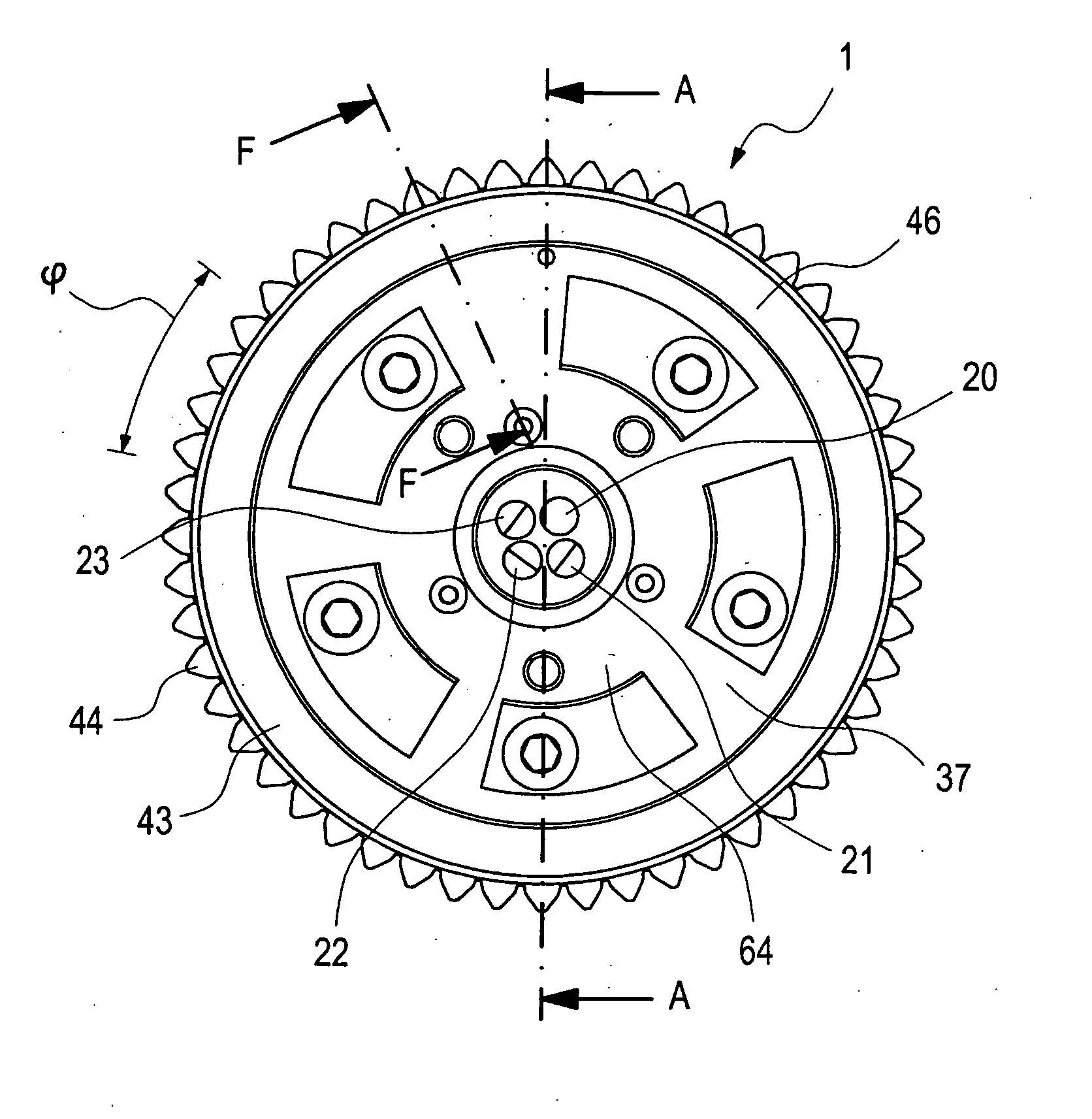
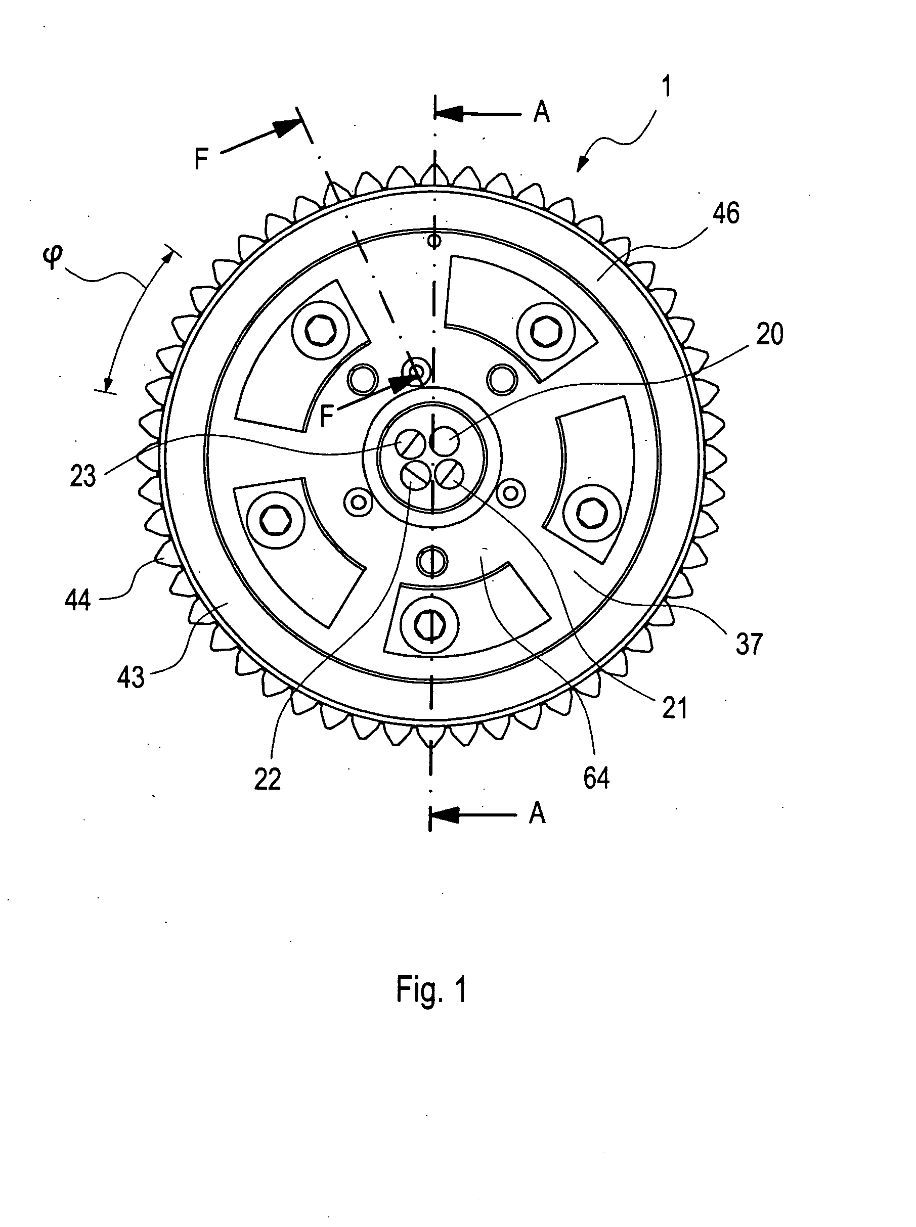
[0034]FIG. 1 shows a cam phasing device 1 which operates as a rotatable vane phasing device. The rotatable vane phasing device can swivel within a certain range of angle φ freely from one side to a second side. The rotation is caused and provoked by oil out of fluid passages 20, 21, 22, 23 by which counter-acting chambers 67, 68 (refer to FIG. 4) are loaded. The cam phasing device 1 can be designed as a double-cam phasing device if driven by o...


PUM


Abstract

The present invention provides a variable valve timing device for an internal combustion engine having a double camshaft. A gas exchange valve control shaft is provided which has first and second concentrically arranged cam shafts that are adjustable in a rotatable manner with respect to each other, by which a cam of the first cam shaft is adjusted in terms of its angle towards a cam of the second cam shaft. A cam phasing device is provided which operates by rotatable vanes provoking a swivelling relative movement between a driven member and an output member. The cam phasing device comprises at least two pivotable vane adjusters. Each pivotable vane adjuster is assigned to one of the two cam shafts. The pivotable vane adjusters are arranged axially one after the other in a direction of a valve control shaft. Each pivotable vane adjuster may be designed as a rotor-type vane adjuster.

Description

FIELD OF THE INVENTION[0001]The present invention refers to a variable valve timing device usable with and for in internal combustion engine.BACKGROUND OF THE INVENTION[0002]EP 1 347 154 A2 shows a swivel-type adjuster that is designated to be used with a control shaft of a variable valve train. A first hydraulic rotatable mechanism is connected to a second hydraulic rotatable mechanism so that by choosing a raw adjustment and by choosing a fine tuning adjustment an exact position for an eccenter of the variable valve train can be picked. Accordingly, it can be said that the angular position of the eccenter is depicted by a two-stage system.[0003]U.S. Pat. No. 2,911,956 describes a plate-like shaft positioner by which a swivel movement of a first plate influences the swivel range of a second plate and so forth.[0004]WO 01 / 12996 shows in FIG. 5a a two stator vane cam phasing system in which a rotor is limited in its swivel movements by rotating first and second stator.[0005]Further, ...

Claims


Application Information

Patent Timeline
IPC IPC(8): F01L1/344
CPCF01L1/047F01L1/34413F01L1/3442F01L2001/34493F01L2001/34469F01L2001/34483F01L2001/34489F01L2001/0473
Inventor HUTCHESON, JACK D.KNECHT, ANDREASPOHL, DIRKBARTON, GLENN A.NANCE, STEPHEN L.COLE, JOE S.
Owner HILITE INT INC
Why Eureka
Try Eureka