Combined touch sensor and LED driver with n-type mosfet protecting touch sensor

a technology of led driver and touch sensor, which is applied in the direction of electric digital data processing, instruments, computing, etc., can solve the problems of affecting the operation of the led driver circuit, and affecting the operation of the touch sensor circuit. , to achieve the effect of preventing the higher operating voltage of the led driver circui

Active Publication Date: 2009-07-09
INTEGRATED DEVICE TECH INC
View PDF15 Cites 23 Cited by
  • Summary
  • Abstract
  • Description
  • Claims
  • Application Information

AI Technical Summary

Benefits of technology

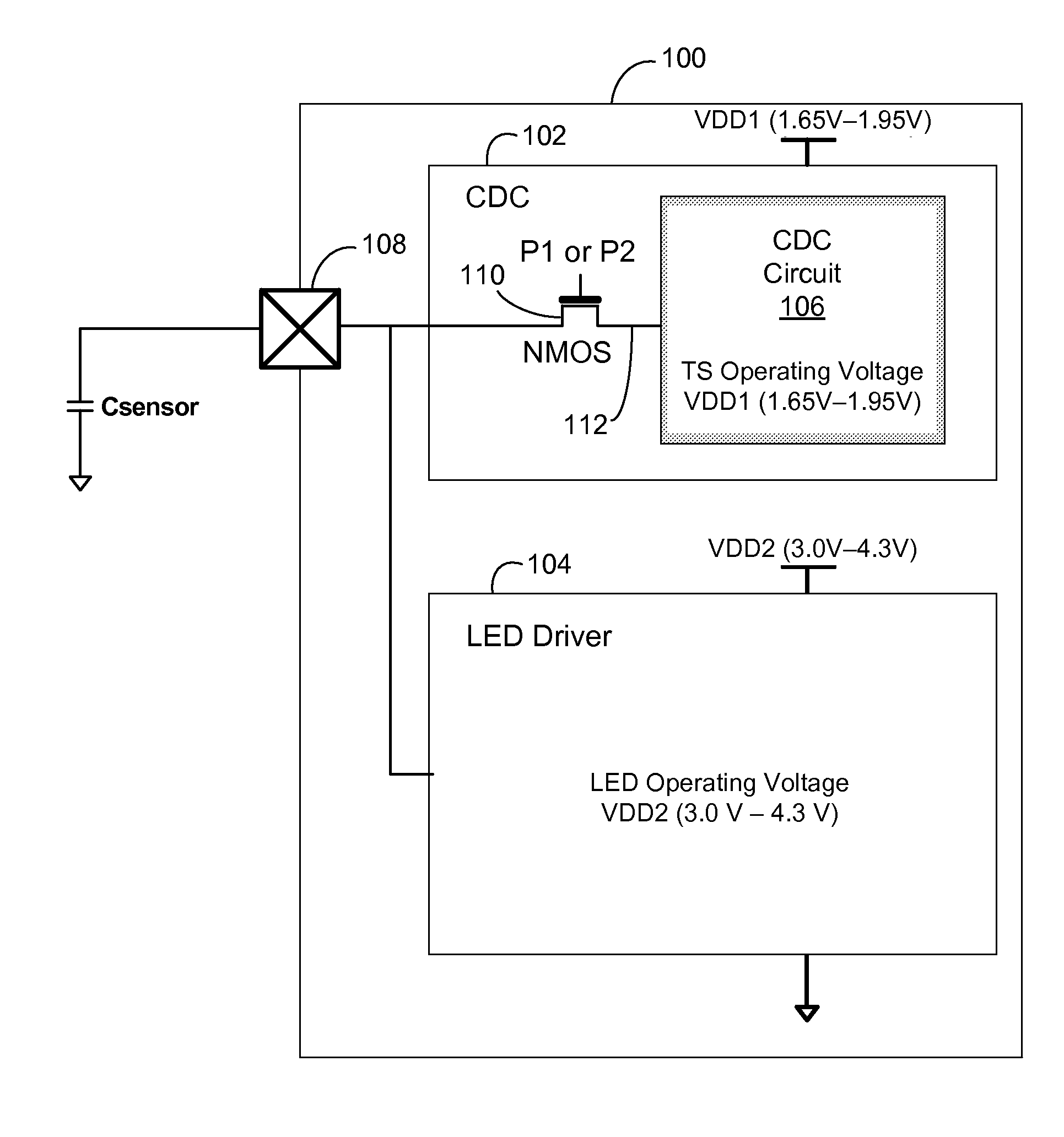
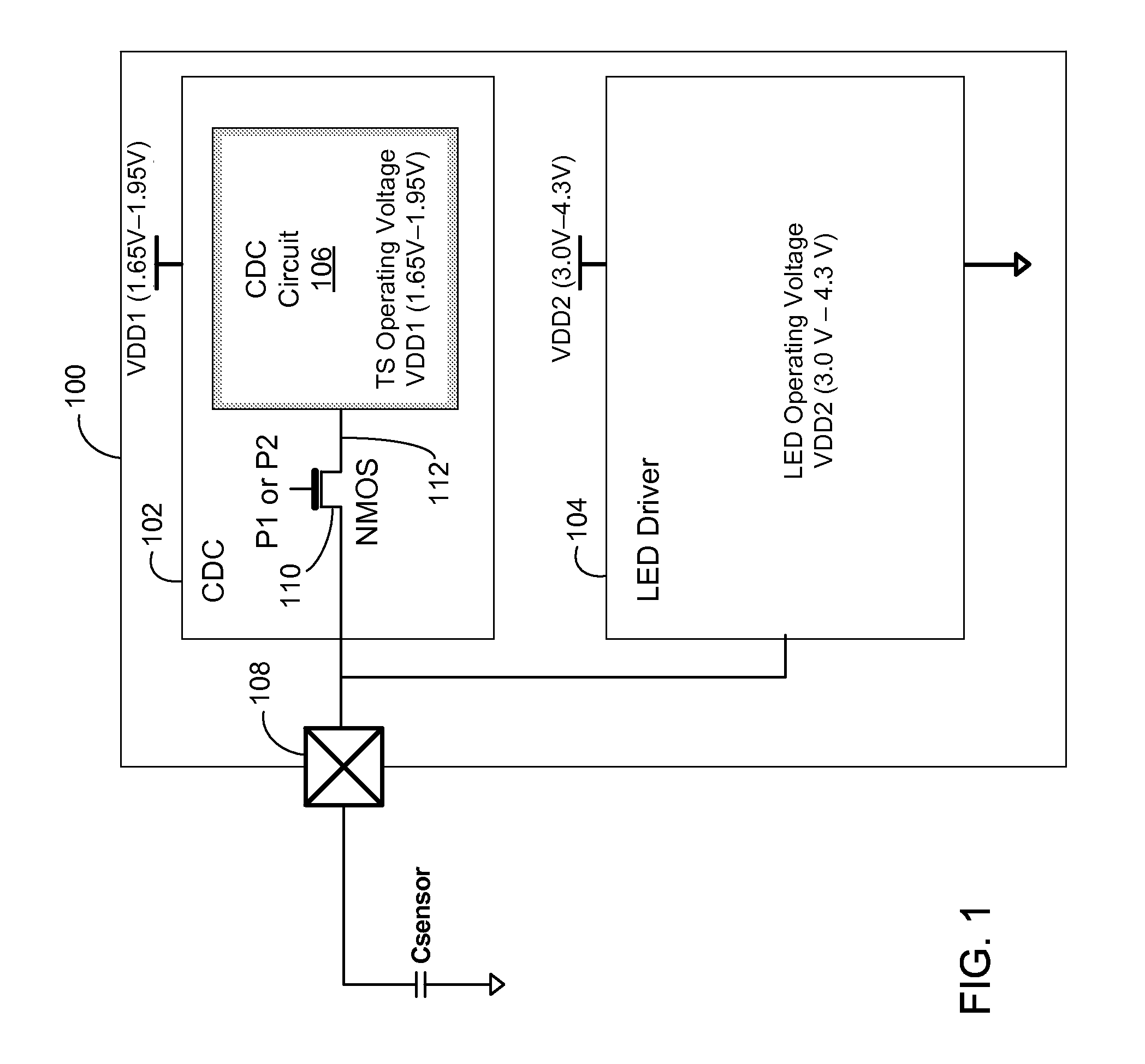
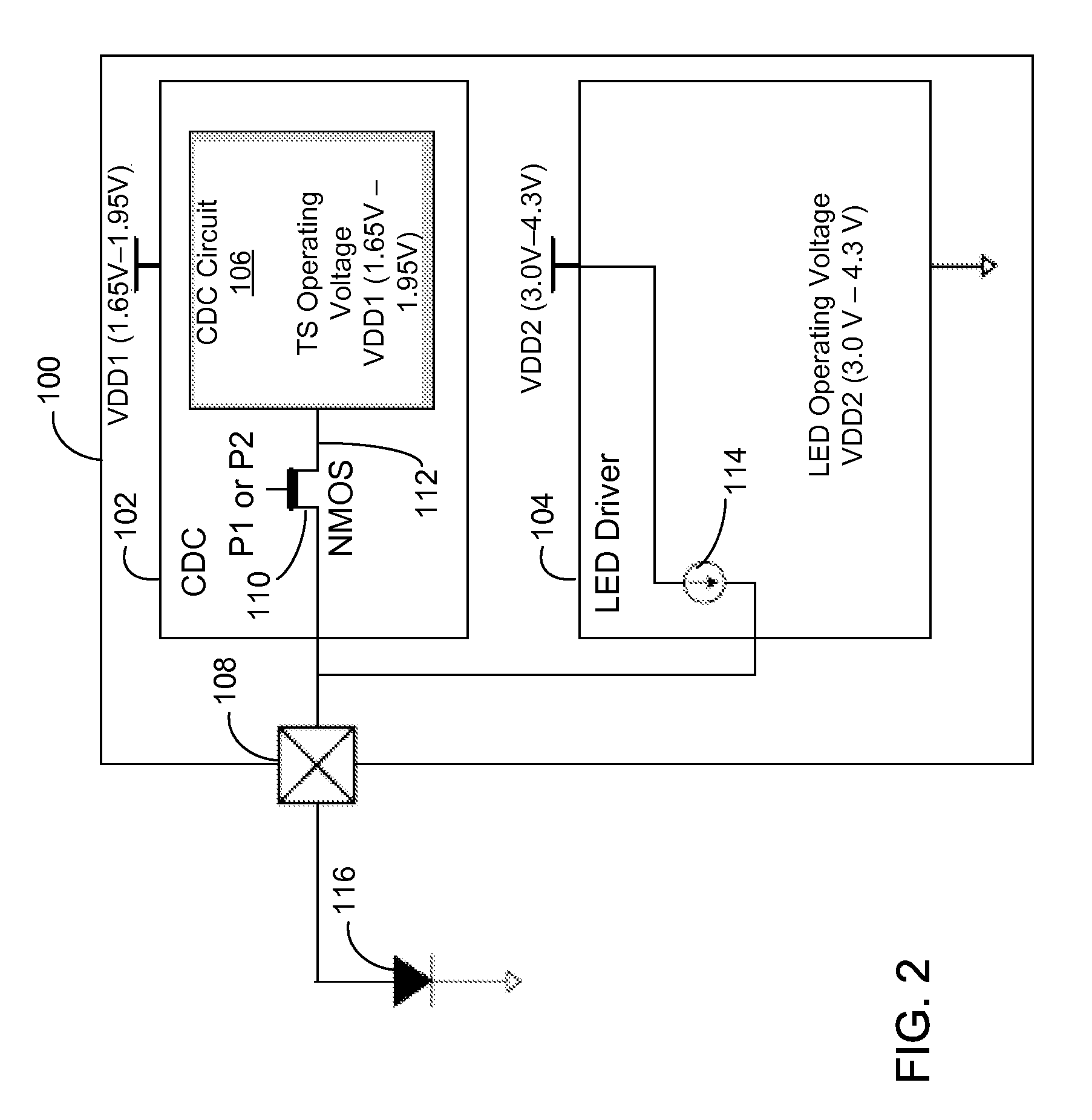
[0009]Embodiments of the present invention include a technique for electrically separating the different operating voltages of an LED driver circuit and touch sensor circuit in a combined touch sensor and LED driver IC. The touch sensor circuit may be a capacitance-to-digital converter (CDC) circuit. More specifically, in one embodiment, a combined touch sensor and light-emitting-diode (LED) driver comprises a touch sensor circuit configured to detect a touch, where the touch sensor circuit is coupled to a common node and configured to operate with a first operating voltage, an LED driver circuit configured to drive an LED if the LED is c...

Problems solved by technology

However, combining the LED driver with touch sensor on one IC with shared ports may present problems due to different operating voltages used in the LED driver and the touch sensor.
Since the LED driver is fabricated on the same IC as the touch sensor and both the LED driver and touc...

Method used


Image

  • Combined touch sensor and LED driver with n-type mosfet protecting touch sensor
  • Combined touch sensor and LED driver with n-type mosfet protecting touch sensor
  • Combined touch sensor and LED driver with n-type mosfet protecting touch sensor

Examples


Embodiment Construction

[0020]The Figures (FIG.) and the following description relate to preferred embodiments of the present invention by way of illustration only. It should be noted that from the following discussion, alternative embodiments of the structures and methods disclosed herein will be readily recognized as viable alternatives that may be employed without departing from the principles of the claimed invention.

[0021]Reference will now be made in detail to several embodiments of the present invention(s), examples of which are illustrated in the accompanying figures. It is noted that wherever practicable similar or like reference numbers may be used in the figures and may indicate similar or like functionality. The figures depict embodiments of the present invention for purposes of illustration only. One skilled in the art will readily recognize from the following description that alternative embodiments of the structures and methods illustrated herein may be employed without departing from the pr...


PUM


Abstract

A combined touch sensor and light-emitting-diode (LED) driver comprises a touch sensor circuit configured to detect a touch, where the touch sensor circuit is coupled to a common node and configured to operate with a first operating voltage, an LED driver circuit configured to drive an LED if the LED is coupled to the common node, where the LED driver circuit is also coupled to the common node and configured to operate with a second operating voltage is higher than the first operating voltage, and an n-type field effect transistor (FET) connected in series between the common node and the touch sensor. The n-type FET prevents the higher operating voltage of the LED driver from affecting the operation of the touch sensor, when a port of the combined touch sensor and LED driver IC is used to drive an LED. The touch sensor may be a capacitance-to-digital converter.

Description

BACKGROUND OF THE INVENTION[0001]1. Field of the Invention[0002]The present invention relates to a combined touch sensor and LED (Light-Emitting Diode) driver.[0003]2. Description of the Related Arts[0004]Modern electronic devices often have both a display device to display information and touch sensors to receive input data. There are a variety of types of touch sensor applications, such as touch screens, touch buttons, touch switches, touch scroll bars, and the like. For example, a cellular telephone or personal digital assistant often has a touch screen and a liquid crystal display (LCD) device overlaid with the touch screen.[0005]LCDs typically require a backlight to provide a light source for the LCD display. White LEDs are being used increasingly as the backlight for LCDs. These white LEDs for backlighting LCDs are typically driven by an LED driver that feeds high, constant sink current through the white LEDs to provide constant luminescence, while the anode of the white LED i...

Claims


Application Information

Patent Timeline
IPC IPC(8): G06F3/041
CPCG06F3/0416G09G2330/04G09G2330/02G09G3/3406
Inventor JEON, YUNG JINLEE, EUN JIN
Owner INTEGRATED DEVICE TECH INC
Why Eureka
Try Eureka