Method for Operating a Switched Mode Power Supply With Return of Primary-Side Stray Energy

a technology of primary-side stray energy and power supply, which is applied in the direction of power conversion systems, dc-dc conversion, instruments, etc., can solve the problems of reducing the efficiency of the power supply, destroying the switch element, and restricting losses, so as to limit the voltage in the discharge circuit and be easily dimensioned

a technology of primary-side stray energy and power supply, which is applied in the direction of power conversion systems, dc-dc conversion, instruments, etc., can solve the problems of reducing the efficiency of the power supply, destroying the switch element, and restricting losses, so as to limit the voltage in the discharge circuit and be easily dimensioned

US20090175054A1Inactive Publication Date: 2009-07-09SIEMENS AG

Image

  • Method for Operating a Switched Mode Power Supply With Return of Primary-Side Stray Energy
  • Method for Operating a Switched Mode Power Supply With Return of Primary-Side Stray Energy
  • Method for Operating a Switched Mode Power Supply With Return of Primary-Side Stray Energy

Examples


Embodiment Construction

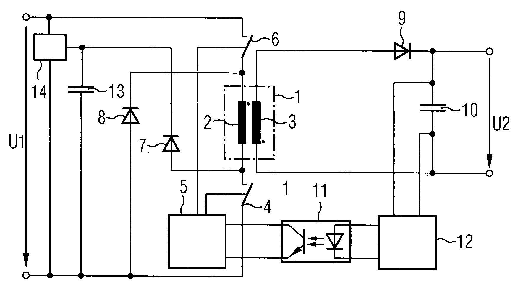
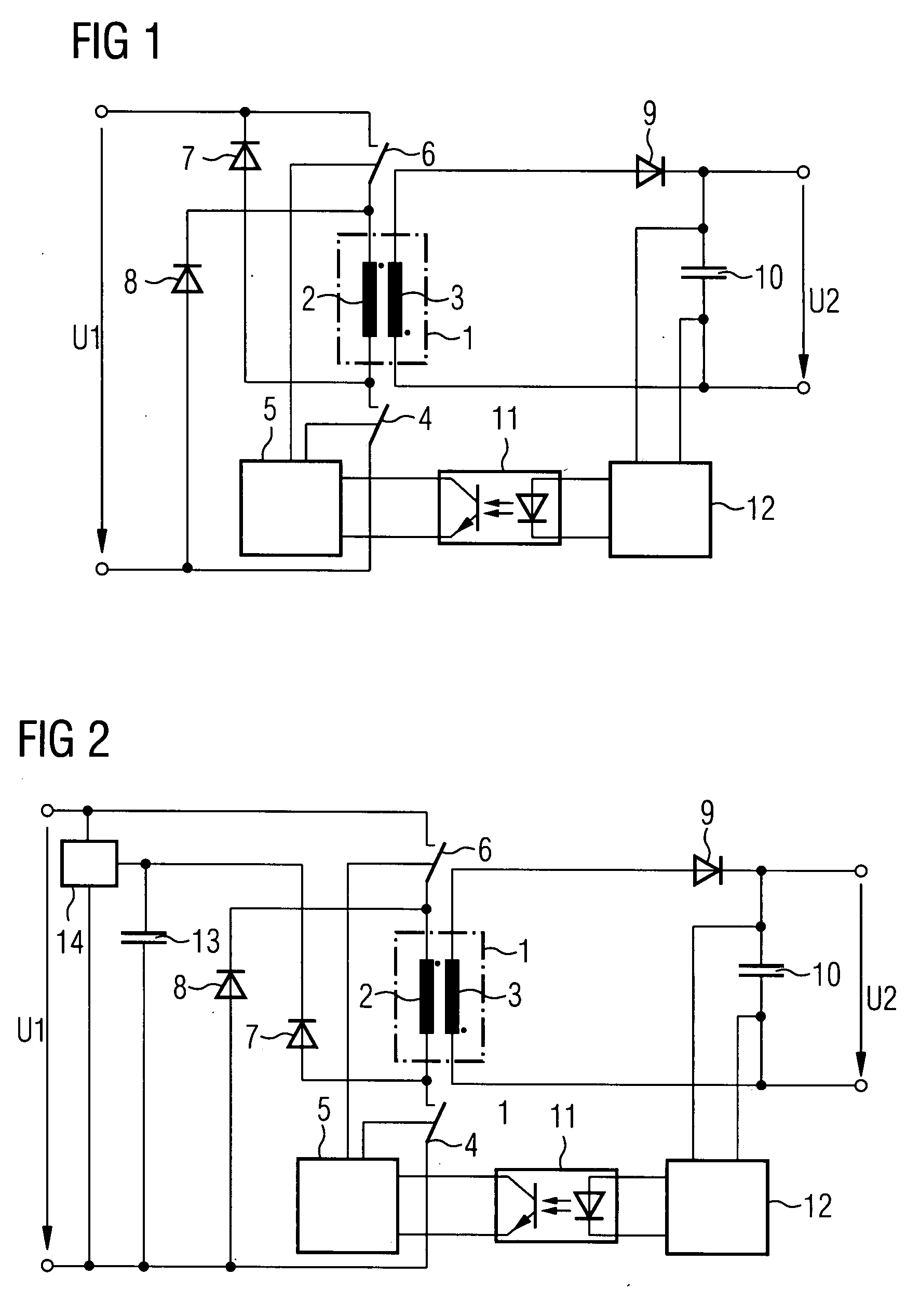
[0035]FIG. 1 shows a switched mode power supply as a flyback converter in simplified form. In this case, the transformer 1 features a primary winding 2 and a secondary winding 3, these being wound in a diametrically opposite manner. On the secondary side, the output voltage U2 is available following rectification by means of a rectifying diode 9 and a smoothing capacitor 10. Attached to this output voltage U2 is an output voltage regulator 12 which transfers an actuating signal via an optocoupler 11 to a controller 5 for load-dependent activation and deactivation of the two switch elements 4 and 6. This controller 5 generally works using pulse-width modulation (PWM) in this case, wherein the power which is transferred via the transformer 1 is determined by the length of the activation times in the context of a clock frequency which normally remains the same. In this case, the clock frequency is significantly higher than the mains frequency.

[0036]The winding interfaces of the primary...


PUM


Abstract

The invention relates to a method for operating a switched mode power supply as an isolating transformer. According to said method, magnetic energy is stored in the core of a transformer during a storage stage via a primary coil that is connected to an intermediate circuit current and the stored magnetic energy is delivered to a load in a subsequent discharge phase, for the most part by means of a secondary coil, a small part of said magnetic energy being discharged on the primary side. The energy that is discharged on the primary side charges a capacitor in such a way that the capacitor current is always held above the secondary current multiplied by the transmittance ratio of the transformer.

Description

CROSS REFERENCE TO RELATED APPLICATIONS[0001]This application is the U.S. National Stage of International Application No. PCT / EP2006 / 060906, filed Mar. 21, 2006 and claims the benefit thereof. The International Application claims the benefits of German application No. 10 2005 016 285.1 filed Apr. 8, 2005, both of the applications are incorporated by reference herein in their entirety.FIELD OF INVENTION[0002]The invention relates to a method for operating a switched mode power supply as a flyback converter wherein, in a capture phase, magnetic energy is stored in the core of a transformer via a primary winding that is attached to an intermediate circuit voltage and wherein, in a subsequent release phase, most of the stored magnetic energy is delivered to a load via a secondary winding and a small part of the magnetic energy is delivered on the primary side. The invention further relates to an arrangement for carrying out the method.BACKGROUND OF THE INVENTION[0003]Switched mode power...

Claims


Application Information

Patent Timeline
09 Jul 2009
Publication
US20090175054A1
IPC
H02M3/335
CPC
H02M3/3353; H02M3/33523; H02M3/335; H02M3/28
Inventors
APPEL, WILHELM; PEPRNY, WOLFGANG