Multiple-Input Multiple-Output Transmission System

a transmission system and multi-input technology, applied in the field of transmission systems, can solve the problems of increasing so as to achieve the effect of raising the retransmission efficiency and reducing the cost of transmission repeating

Inactive Publication Date: 2009-07-09
FUJITSU LTD
View PDF13 Cites 24 Cited by
  • Summary
  • Abstract
  • Description
  • Claims
  • Application Information

AI Technical Summary

Benefits of technology

[0019]Accordingly, an object of the present invention is to improve error rate by re-transmission and raise re-transmission efficiency.
[0026]Means for deciding the transmit antenna of the transmit station or receive station decides the re-transmission transmit antenna in the following manner, by way of example: The transmit antenna deciding means ranks transmit antennas in order of descending superiority of the states of the propagation paths and, when a substream requiring re-transmission is to be re-transmitted, performs reallocation of the transmit antennas in an order that is the reverse of the order of ranking in such a manner that a data stream requiring re-transmission transmitted the previous time from a transmit antenna for which the state of the propagation path is poorest will be transmitted from a transmit antenna for which the state of the propagation path is best. As a result, in a case where re-transmission is performed in a MIMO system, the error rate of data transmitted the previous time from an antenna whose propagation path conditions were poor can be improved and re-transmission efficiency raised. Further, in a case where re-transmission is performed in a MIMO system, transmission can be made to succeed with a small number of re-transmissions and re-transmission efficiency can be raised.

Problems solved by technology

Generally, in a MIMO system, a transmission error tends to occur in a data stream that has been transmitted from an antenna for which the state of propagation path is inferior to other transmit antennas.
Since the antenna for which the state of the propagation path is poor changes owing to fading fluctuation, the data stream that gives rise to the transmission error also changes with time.
Further, in a MIMO system, transmission error tends to occur also in a case where the correlation between antennas increases owing to the propagation environment.
Since the state of the propagation path changes in a complex manner, there are instances where a transmission error tends to occur in a specific data stream owing to an increase in correlation between specific antennas.
Thus, with a MIMO system, there is a tendency for error to concentrate in a certain specific data stream, and the data stream in which error concentrates changes with time.
Consequently, a problem which arises is that the improvement in error rate by re-transmission is diminished and it becomes difficult to obtain re-transmission control gain.
The problem becomes particularly acute if the change in fading or multipath environment is slow in comparison with re-transmission interval (round-trip time).
However, the first prior art does not improve error rate by re-transmission.
Although the second prior art relates to re-transmission control, it does not improve error rate by re-transmission and does not raise re-transmission efficiency.

Method used


Image

  • Multiple-Input Multiple-Output Transmission System
  • Multiple-Input Multiple-Output Transmission System
  • Multiple-Input Multiple-Output Transmission System

Examples


first embodiment

(A) First Embodiment

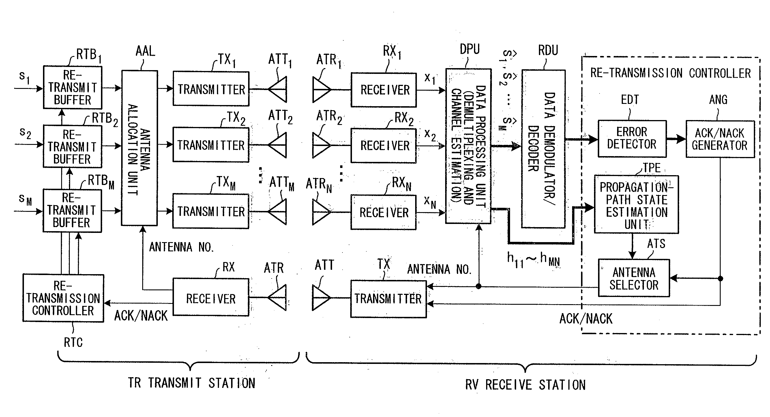
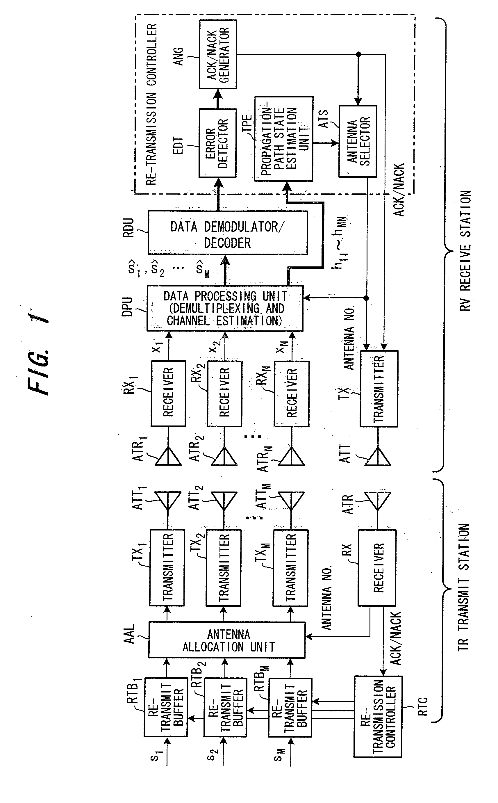
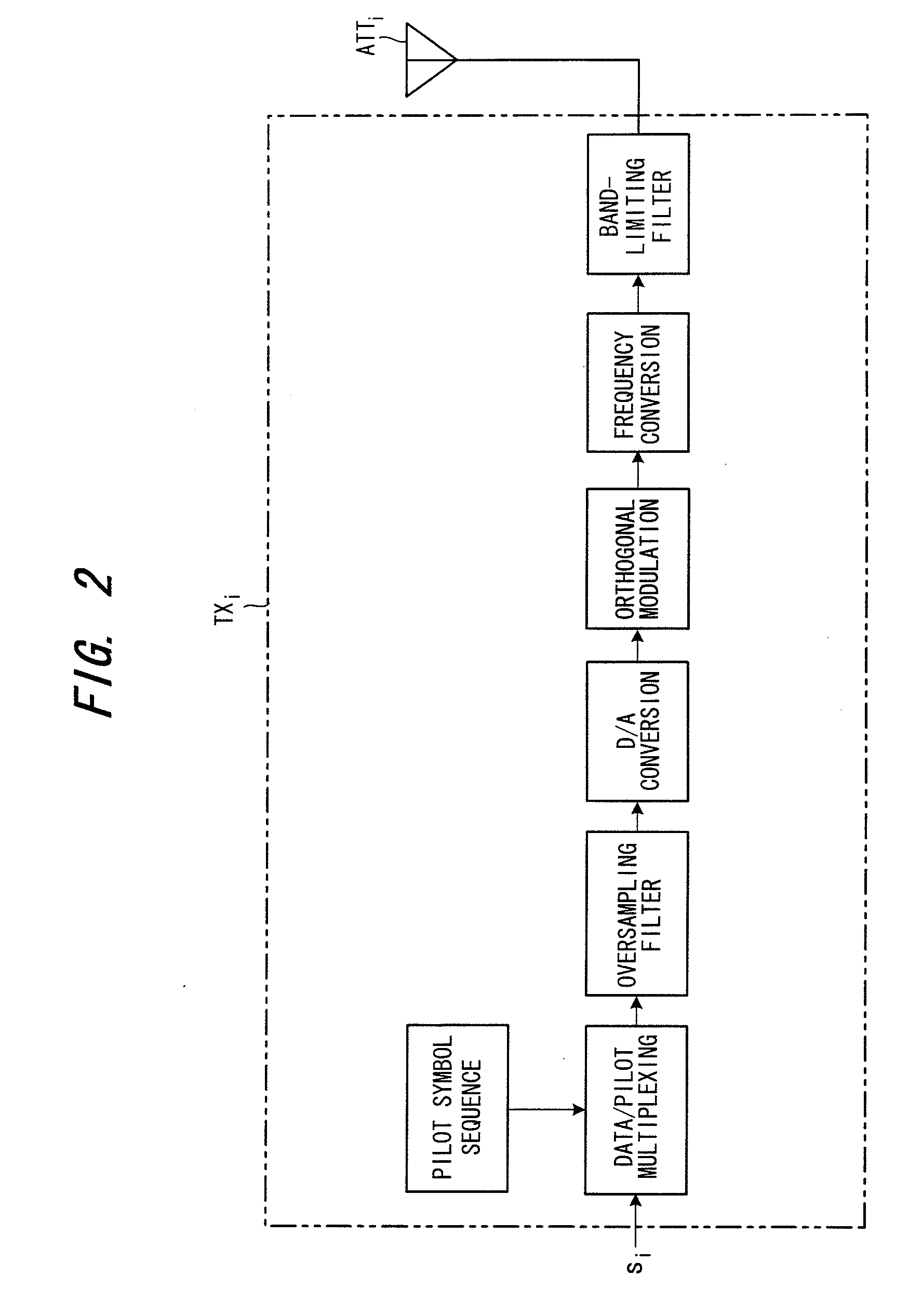
[0044]FIG. 1 is a diagram illustrating the architecture of a multiple-input multiple-output transmission system according to a first embodiment, FIG. 2 is a diagram illustrating the structure of a transmitter in the multiple-input multiple-output transmission system, and FIG. 3 is a diagram illustrating the structure of a receiver in the multiple-input multiple-output transmission system. Components identical with those of the example of the prior art are designated by like reference characters.

[0045]Overview of First Embodiment

[0046]A first embodiment detects ACK / NACK for every data stream in the receive station RV and, at the same time, estimates the state of the propagation path for every antenna using pilot symbols orthogonally multiplexed for every transmit antenna. Usually a data stream for which ACK will hold is transmitted from an antenna for which the state of the propagation path is good, and a data stream for which NACK will hold is transmitted from an...

second embodiment

(B) Second Embodiment

[0058]FIG. 6 is a diagram illustrating the architecture of a multiple-input multiple-output transmission system according to a second embodiment. Components identical with those of the first embodiment are designated by like reference characters.

[0059]Overview of Second Embodiment

[0060]In the first embodiment, a transmit antenna that is to re-transmit a NACK data stream is decided by the antenna selector ATS and reported to the transmit station. In the second embodiment, however, the state of the propagation path is transmitted to the transmit station. On the basis of the state of the propagation path, an antenna selector ATSL in the transmit station decides the transmit antenna that is to perform re-transmission.

[0061]More specifically, in the first embodiment, the arrangement is such that the antenna used in re-transmission is decided by the receive station. In the second embodiment, however, the arrangement is such that the antenna is decided by the transmit ...

third embodiment

(C) Third Embodiment

[0067]FIG. 7 is a diagram illustrating the structure of a receiver according to a third embodiment. This embodiment differs from the second embodiment in that a re-transmission combiner RTC is provided. It should be noted that although the transmit station is not illustrated, it has a structure identical with that of the second embodiment.

[0068]In order to improve the reception quality of the re-transmission signal, the re-transmission combiner RTC combines the re-transmission packet and a packet transmitted previously and for which NACK was detected. That is, an error-containing packet for which reception has failed and a re-transmission request (NACK information) been issued is stored in a re-transmission combining buffer by the re-transmission combiner RTCB. When a packet (data stream) that has been re-transmitted is received, the re-transmission combiner RTCB combines the re-transmission packet and the packet (data stream) inside the buffer. By thus combining...


PUM


Abstract

In a multiple-input multiple-output transmission system (MIMO system), a receive station detects whether or not there is an error in each data stream, estimates the state of the propagation path of each transmit antenna and reports, to the transmitting side, re-transmission necessary / unnecessary information, for every data stream, created based upon whether or not there is an error, and the state of the propagation path of each transmit antenna. A transmit station decides a transmit antenna that transmits a data stream requiring re-transmission, based upon the reported state of the propagation path of each transmit antenna, and re-transmits the data stream requiring re-transmission from the transmit antenna decided.

Description

CROSS-REFERENCE TO RELATED APPLICATION[0001]This application is a divisional of U.S. application Ser. No. 11 / 233,189 filed Sep. 22, 2005, which is a continuation of International Application PCT / JP03 / 08297, filed on Jun. 30, 2003, pending at the time of filing of this continuation application, the contents of which are herein wholly incorporated by reference.BACKGROUND OF THE INVENTION[0002]This invention relates to a transmission system having a multiple-input multiple-output (MIMO) architecture. More particularly, the invention relates to a multiple-input multiple-output transmission system, which has a plurality of transmit antennas and receive antennas and is capable of high-speed data transmission, and to a transmit station and receive station in this system.[0003]Of special interest in present-day wireless communication systems is a spatial multiplex transmission technique in which transmission capacity is increased in proportion to the number of transmit antennas by transmitt...

Claims


Application Information

Patent Timeline
Patent Type & Authority Applications(United States)
IPC IPC(8): H04K1/10H04B7/024H04B7/0413H04B7/06H04B7/08H04L1/00H04L1/06H04L1/16H04L1/18
CPCH04B7/02H04B7/061H04B7/0691H04L1/0003H04L1/0009H04L1/06H04L1/1893H04L1/08H04L1/1607H04L1/18H04L1/1835H04L1/1874H04L1/0618H04B7/024H04B7/0413
Inventor SEKI, HIROYUKITANAKA, YOSHINORIJITSUKAWA, DAISUKE
Owner FUJITSU LTD
Why Eureka
Try Eureka